AN/MRN-1
The AN/MRN-1 was an instrument approach localizer used by the Army Air Force during and after World War II. It was standardized on 3 July 1942. It replaced the SCR-241, and was a component of SCS-51.
Use
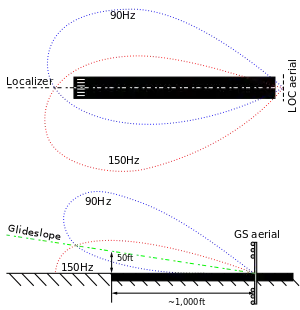
The transmitter provides a signal to guide the RC-103 equipped aircraft to the centerline of a runway. The set radiates two intersecting field patterns, one of which is modulated at an audio frequency of 90 cycles per second, and the other at an audio frequency of 150 cycles per second. The shape of the radiated patterns is such that they intersect in a vertical plane called the "course", which can be oriented (by positioning the truck) to intersect the ground in a line which coincides with the center-line of a landing runway. The range of the equipment is a function of the elevation of the receiving antenna: approximately 40 miles at an elevation of 2,500 feet, 70 miles at 6,000 feet, and 100 miles at 10,000 feet. The transmitter, BC-751-A has a frequency range from 108.3 to 110.3 Mc. power output is 25 Watts.
- AN/CRN-3 is the same equipment except without the K-53 truck, thereby making it air transportable, components are housed in a tent.

Components
The AN/MRN-1 is mounted in a K-53 truck and is made up of the following components.
- BC-915 control box
- BC-751 radio transmitter
- BC-752 Modulator and bridge
- BC-753 course detector fixed
- BC-754 course detector portable
- BC-755 field intensity meter
- BC-777 indicator (alarm)
- RC-109 antenna (5 alford loops in a horizontal plane)
- An SCR-610 is provided for ground communications
- power is provided by a PE-141 generator (115 volts)
Aircraft components
The RC-103-A is an airborne localizer receiver used to indicate a landing course in conjunction with the AAF instrument approach system. signals received from a transmitter, located at one end of the runway to be used, are fed into the cross-pointer indicator to indicate "on course", "fly right" or "fly left". Audio indication is also provided.
- Antenna system AS-27/ARN-5 is used with the dual installation of the localizer and glide path receivers. Antenna AN-100 is used when only the localizer receiver is installed in the aircraft.
- RC-103 components include
- Indicator I-101-C
- BC-732 control box
- BC-733 Receiver W/ DM-53 Dynamotor
- AN-100 Antenna (localizer only)
- AS-27/ARN-5 Antenna system (combination)
See also
References
- TM 11-227 Signal Communication Directory. Dated 10 April 1944.
- TM 11-487 Electrical Communication systems Equipment. Dated 2 October 1944.
- Graphic Survey of Radio and Radar Equipment Used by the Army Airforce. Section 3, Radio Navigation Equipment. Dated May 1945.
- TO 30-100F-1. Dated 1943.
Further reading
- Erik M. Conway (2006). Blind Landings: Low-Visibility Operations in American Aviation, 1918–1958. JHU Press. p. 108. ISBN 978-0-8018-8449-8.
External links
- http://www.footnote.com/image/#46938757 Archived 2010-03-14 at the Wayback Machine exterior
- http://aafcollection.info/items/documents/view.php?file=000149-01-03.pdf TO 30-100F-1 1943
- http://www.designation-systems.net/usmilav/jetds/an-c.html
- http://www.flightglobal.com/pdfarchive/view/1949/1949%20-%200728.html SCS-51
- http://aafradio.org/NASM/RHAntennas.htm antenna systems
- http://jproc.ca/rrp/rrp3/argus_bc733d.jpg BC-733