Aviation obstruction lighting
Aviation obstruction lighting is used to enhance the visibility of structures or fixed obstacles which may conflict with the safe navigation of aircraft. Obstruction lighting is commonly installed on towers, buildings, and even fences located in areas where aircraft may be operating at low altitudes. In certain areas, some aviation regulators mandate the installation, operation, color, and/or status notification of obstruction lighting. For maximum visibility and collision-avoidance, these lighting systems commonly employ one or more high-intensity strobe or LED devices which can be seen by pilots from many miles away from the obstruction.
Lamp types
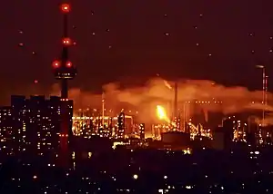
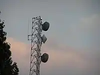
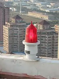
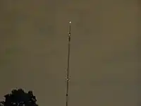
The lights generally come in two forms:
- Red lamps that are either constantly illuminated or turn on and off slowly in a cycle of a few seconds.
- White xenon flash lamps.
Both types were in use in the United Kingdom until recently. New regulations stipulate the use of red lamps at nighttime only. Xenon flashers are gradually being phased out.
In the United States and Canada, there are several types of lights:
- Obstruction lights (that are constantly illuminated)
- Red beacons/red strobes
- High-intensity white (strobe) lights
- Medium-intensity white (strobe) lights
Traditionally, red lamps (or beacons) use incandescent filament bulbs. To improve the otherwise quite short lifespan, they are made with a ruggedised design and are run below normal operating power (under-running). A recent development has been the use of arrays of high-power red LEDs in place of incandescent bulbs, which has only been possible since the development of LEDs of sufficient brightness. LED-based lamps have a significantly longer lifespan than incandescent bulbs, thus reducing maintenance costs and increasing reliability. Several manufacturers have also developed medium-intensity white strobes based on LED technology to replace xenon. Xenon flashers, whilst more visually impressive, tend to require frequent replacement and so have become a less favoured option. With the advent of LEDs, white strobes are still somewhat desired.
It is common to find structures using white xenon flashers/white strobes during the daytime, and red lights at night. Red lights are commonly found to be used in urban areas, since it is easier for pilots to spot them from above. White strobes (that flash round the clock) may also be used in urban areas. It has been recommended that flashing white strobes should not be used in densely populated areas, as the lights usually merge with background lighting at nighttime, making it difficult for pilots to spot them, aggravating the hazard. In addition, residents near the lit structure will complain of light trespass. In rural areas, red beacons/strobes may also be used during nighttime. White strobes are (sometimes) preferred since they reduce the maintenance cost (i.e. no maintenance of painting, no red side lights) and there are no background lights that would blend with the strobes.
There are a medium-intensity white strobe and a high-intensity white strobe. Medium-intensity white strobes are usually used on structures that are between 200 and 500 feet (61 and 152 meters). If a medium white strobe is used on a structure greater than 500 feet (150 meters), the structure must be painted. The common medium white strobe flashes 40 times per minute, at an intensity of 20,000 candelas for daytime/twilight, and 2,000 candelas at nighttime.
A high-intensity white strobe is used on structures that are taller than 700 feet (210 meters). These lights provide the highest visibility both day and night. Unlike a medium strobe, a high-intensity strobe does not provide 360° coverage; this requires the use of at least 3 high strobes at each level. On the other hand, it reduces maintenance costs (i.e. no painting). If the structure has an antenna at the top that is greater than 40 feet, a medium-intensity white strobe light must be placed above it rather than below. The common high white strobe flashes 40 times per minute, at an intensity of 270,000 candelas for daytime, 20,000 candelas at twilight, and 2,000 candelas at nighttime.[1]
Dual lighting is a system in which a structure is equipped with white strobes for daytime use, and red lights for nighttime use. In urban areas, these are commonly preferred since it usually exempts a structure from painting requirements. One advantage to the dual system is that when the uppermost red lights fail, the lighting switches onto its backup lighting system, which uses the white strobes (at its night intensity) for nighttime. In the US and Canada, red incandescent beacons are slowly being withdrawn from service and being replaced with red strobes or red LEDs.
For high-tension power lines, white strobes are equipped to flash 60 times per minute, using the same intensities as stated above. Unlike common white strobes, these strobes are specified not to flash simultaneously. The FAA-mandated flash pattern is middle, top, and bottom to provide "a unique signal that pilots should interpret as a warning that catenary wires are in the vicinity of the lights."[2]
Transmission towers
On electric transmission towers, lights may be energized either from the electric field surrounding the energized conductor, or the magnetic field produced by current through the conductor. The first approach takes advantage of the high electric potential gradient around conductors. The second approach is based on Faraday's law of induction involving magnetic flux flowing through a circuit which energizes the warning light.
Use and positioning
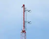
These lights can generally be found attached to any tall structure such as broadcast masts and towers, water tanks located on high elevation, electricity pylons, chimneys, tall buildings, cranes and wind turbines. Shorter structures that are located close to airports may also require lighting; an example of such is the south scoreboard at Lambeau Field in Green Bay, Wisconsin built in 2013, which is the tallest structure in the general area of nearby Austin Straubel International Airport. The International Civil Aviation Organization (ICAO) sets standards, usually adopted worldwide, for the performance and characteristics of aviation warning lamps.
Lights are usually arranged in clusters of two or more around the structure at specific heights on the tower. Frequently there will be a set at the top, and then one or more sets equally spaced down the structure. The United Kingdom's Belmont mast has nine clusters of red lamps spaced equally along the full height of the mast.
Conductor marking lights
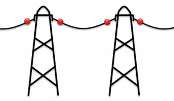
Conductor marking lights are sometimes used (in conjunction with overhead wire markers) to make overhead power lines more visible. Because power lines are often suspended between widely spaced masts, they present a particularly grave hazard to low flying aircraft. A simple and cost-effective solution to this problem is installing marking lights directly on the wires, but there are significant technical difficulties to low-cost power extraction from a distribution system which carries high voltages and wide-range AC current.

The ideal warning light must be able to power itself while clamped to a single wire of the line. Lights may be powered either from the electric field surrounding the energized wire, or the magnetic field produced by current through the wire. The first approach takes advantage of the high electric potential gradient between conductors, but a strong enough capacitive coupling is requested to allow capacitive extraction of the power required from the warning light. This means that long conductors must be suspended parallel to the line using glass/ceramic isolators: in fact several meters of suspended conductor are generally required, total length being inversely proportional to the line voltage. The second approach is based on Faraday's law of induction involving magnetic flux flowing through a circuit which powers the warning light.
Non-standard aircraft warning lights
On some tall structures there are or were non-standard aircraft warning lights installed.
- The mast of Deutschlandsender Herzberg/Elster had no aircraft warning lamps installed. It was instead lit by skybeamers mounted on small masts near the tower. This method was chosen as the mast was a mast radiator insulated against ground and for feeding the lamps on the mast otherwise special devices like Austin transformers would be required.
- Stuttgart TV Tower carries a rotating light assembly mounted atop, like used on lighthouses. These rotating lights were called aerial lighthouses in the world of European aviation and airway beacons in the aviation of the United States. Such lamps were also used on other towers and on top of mountains in the earlier days of aviation until the end of the 1950s.
- The last operational aerial lighthouse in the United Kingdom is on top of the cupola over the RAF College main hall at RAF Cranwell.
- In Spain there are only 12 operational rotating lights or aerial lighthouses in use. They are all of them on top of very high towers in military airbases.
- Blosenbergturm in Beromünster also has an aerial lighthouse or rotating lamp above the cabin. In contrast to the Stuttgart TV Tower it is less bright and only operated at dawn.
- In the United States aerial lighthouses are still in use on top of the mountains of Montana.
- The Eiffel Tower in Paris, had an aerial lighthouse between 1947 and 1970, when the French aviation authority estimated that it was no longer needed to help aerial navigation, and set instead the standard warning lamps on top of the tower. In 2000 it was decided to uninstall the warning lamps and install again an aerial lighthouse visible by airplanes at 80 km. of distance.
- In Finland the aerial lighthouse that was built in 1929 on top of the Suomenlinna Church by the aviation authorities in Helsinki, is still in use.
- The main masts of Mühlacker radio transmitter and the former Konstantynów Radio Mast also have aircraft warning lights at the outermost bases of their anchor guys.
- Conductor marking lights and Balisors are sometimes used for marking power lines.
- The Obstacle Collision Avoidance System allows the standard lights to remain off until an aircraft is within a given radius, allowing for a significant decrease in light pollution. The OCAS system also provides audio warnings.
Aircraft warning paint
Aviation laws also require towers and masts to be painted with equal length stripes of international orange and white paint along their length to improve daytime visibility. This paint scheme is usually required on towers over 200 feet tall, but may vary from state to state and near airports internationally. Because such a paint scheme is expensive to apply, antenna towers and masts are often built to heights just below the level of requirement. Antenna towers and masts often also have other aircraft warning features located at equal distances along their height and at their tops. These may include high powered strobe lights or LED lights in either red, white, or both colors in an alternating pattern. In such a case red is employed at night, while a white strobe is usually used during daylight hours.[2][3]
Environmental impact
Warning lights on ground-based towers and buildings contribute to both light pollution and towerkill of birds.
Gallery
 An antenna tower stands 446 feet (136 m) tall in Springfield, MO with its red and white aircraft warning paint visible
 An antenna tower 146 feet (45 m) tall in San Antonio, TX with its red and white aircraft warning paint visible
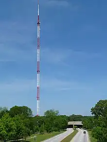 An antenna tower 1,075 feet (328 m) tall in Atlanta, GA with its red and white aircraft warning paint visible
 Hersheypark roller coaster at night with white aviation obstruction lights which enhance the visibility of the ride and act as special effects.
References
- Tower Lighting Guidelines
- Federal Aviation Administration (4 December 2015). "AC 70/7460-1L - Obstruction Marking and Lighting" (PDF). Archived from the original (PDF) on 7 April 2022. Retrieved 30 June 2022.
- Transport Canada (17 October 2013). "Obstruction Marking and Lighting: §6.4 Marking" (PDF). Government of Canada. p. 62. Archived from the original (PDF) on 22 November 2013. Retrieved 30 June 2022.