Airspeed indicator
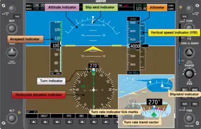
The airspeed indicator (ASI) or airspeed gauge is a flight instrument indicating the airspeed of an aircraft in kilometres per hour (km/h), knots (kn), miles per hour (MPH) and/or metres per second (m/s). The recommendation by ICAO is to use km/h, however knots is currently the most used unit. The ASI measures the pressure differential between static pressure from the static port, and total pressure from the pitot tube. This difference in pressure is registered with the ASI pointer on the face of the instrument.[1]
Colour-coded speeds and ranges
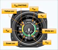
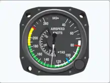
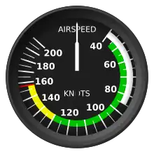
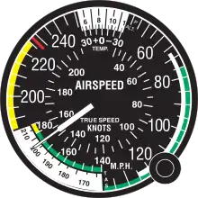
The ASI has standard colour-coded markings to indicate safe operation within the limitations of the aircraft. At a glance, the pilot can determine a recommended speed (V speeds) or if speed adjustments are needed. Single and multi-engine aircraft have common markings. For instance, the green arc indicates the normal operating range of the aircraft, from VS1 to VNO. The white arc indicates the flap operating range, VSO to VFE, used for approaches and landings. The yellow arc cautions that flight should be conducted in this range only in smooth air, while the red line (VNE) at the top of the yellow arc indicates damage or structural failure may result at higher speeds.[1]: 8–9
The ASI in multi-engine aircraft includes two additional radial markings, one red and one blue, associated with potential engine failure. The radial red line near the bottom of green arc indicates Vmc, the minimum indicated airspeed at which the aircraft can be controlled with the critical engine inoperative. The radial blue line indicates VYSE, the speed for best rate of climb with the critical engine inoperative.[2]
Operation
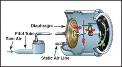
The ASI is the only flight instrument that uses both the static system and the pitot system. Static pressure enters the ASI case, while total pressure flexes the diaphragm, which is connected to the ASI pointer via mechanical linkage. The pressures are equal when the aircraft is stationary on the ground, and hence shows a reading of zero. When the aircraft is moving forward, air entering the pitot tube is at a greater pressure than the static line, which flexes the diaphragm, moving the pointer. The ASI is checked before takeoff for a zero reading, and during takeoff that it is increasing appropriately.[1]: 8–10 [3][4]
The pitot tube may become blocked, because of insects, dirt or failure to remove the pitot cover. A blockage will prevent ram air from entering the system. If the pitot opening is blocked, but the drain hole is open, the system pressure will drop to ambient pressure, and the ASI pointer will drop to a zero reading. If both the opening and drain holes are blocked, the ASI will not indicate any change in airspeed. However, the ASI pointer will show altitude changes, as the associated static pressure changes. If both the pitot tube and the static system are blocked, the ASI pointer will read zero. If the static ports are blocked but the pitot tube remains open, the ASI will operate, but inaccurately.[1]: 8–10, 8–11
Types of airspeeds
There are four types of airspeed that can be remembered with the acronym ICE-T. Indicated airspeed (IAS), is read directly off the ASI. It has no correction for air density variations, installation or instrument errors. Calibrated airspeed (CAS) is corrected for installation and instrument errors. Equivalent airspeed (EAS) is calibrated airspeed (CAS) corrected for the compressibility of air at a non-trivial Mach number. True airspeed (TAS) is CAS corrected for altitude and nonstandard temperature. TAS is used for flight planning. TAS increases as altitude increases, as air density decreases. TAS may be determined via a flight computer, such as the E6B. Some ASIs have a TAS ring. Alternatively, a rule of thumb is to add 2 percent to the CAS for every 1,000 ft (300 m) of altitude gained.[1]: 8–8, 8–9
Jet aircraft
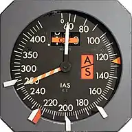
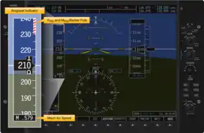
Jet aircraft do not have VNO and VNE like piston-engined aircraft, but instead have a maximum operating speed expressed in knots, VMO and Mach number, MMO. Thus, a pilot of a jet aeroplane needs both an airspeed indicator and a Machmeter, with appropriate red lines. An ASI will include a red-and-white striped pointer, or "barber's pole", that automatically moves to indicate the applicable speed limit at any given time.[2]: 15–7
Angle of attack and Lift Reserve Indicators
An aeroplane can stall at any speed, so monitoring the ASI alone will not prevent a stall. The critical angle of attack (AOA) determines when an aircraft will stall. For a particular configuration, it is a constant independent of weight, bank angle, temperature, density altitude, and the center of gravity of an aircraft. An AOA indicator provides stall situational awareness as a means for monitoring the onset of the critical AOA. The AOA indicator will show the current AOA and its proximity to the critical AOA.[1]: 5–26, 5–27
Similarly, the Lift Reserve Indicator (LRI) provides a measure of the amount of lift being generated. It uses a pressure differential system to provide the pilot with a visual representation of reserve lift available.[5]
See also
References
- Pilot's Handbook of Aeronautical Knowledge (PDF). U.S. Dept. of Transportation, FAA. 2016. 8-8. Retrieved 10 October 2018.
- Airplane Flying Handbook, FAA-H-8083-3B (PDF). U.S. Dept. of Transportation, FAA. 2016. 12-2. Retrieved 10 October 2018.
- "How Aircraft Instruments Work". Popular Science. March 1944. pp. 117, mid page.
- "How Aircraft Instruments Work". Popular Science. March 1944. pp. 116.
- "Lift Reserve Indicator". Sonex Builders & Pilots Foundation. Sonex Foundation. Archived from the original on 11 October 2018. Retrieved 10 October 2018.
Additional reading
- Airplane Flying Handbook. U.S. Government Printing Office, Washington D.C.: U.S. Federal Aviation Administration. 2004. FAA-8083-3A. Archived from the original on 2011-06-30.
- Instrument Flying Handbook (PDF). U.S. Government Printing Office, Washington D.C.: U.S. Federal Aviation Administration. 2005-11-25. FAA-H-8083-15.
- Pilot's Handbook of Aeronautical Knowledge. U.S. Government Printing Office, Washington D.C.: U.S. Federal Aviation Administration. 2003. FAA AC 61-23C. Archived from the original on 2015-07-01.
Installing and flying the Lift Reserve Indicator, article and photos by Sam Buchanan http://home.hiwaay.net/~sbuc/journal/liftreserve.htm
![]() This article incorporates public domain material from Airplane Flying Handbook. United States Government.
This article incorporates public domain material from Airplane Flying Handbook. United States Government.
![]() This article incorporates public domain material from Instrument Flying Handbook (PDF). United States Government.
This article incorporates public domain material from Instrument Flying Handbook (PDF). United States Government.
![]() This article incorporates public domain material from Pilot's Handbook of Aeronautical Knowledge. United States Government.
This article incorporates public domain material from Pilot's Handbook of Aeronautical Knowledge. United States Government.
