Blackmer RMS detector
The Blackmer RMS detector is an electronic true RMS converter invented by David E. Blackmer in 1971. The Blackmer detector, coupled with the Blackmer gain cell, forms the core of the dbx noise reduction system and various professional audio signal processors developed by dbx, Inc.
Unlike earlier RMS detectors that time-averaged algebraic square of input signal, the Blackmer detector performs time-averaging on the logarithm of the input, being the first successful, commercialized instance of log-domain filter.[1] The circuit, created by trial and error, computes root mean squared of various waveforms with high precision, although exact nature of its operation was not known to the inventor. First mathematical analysis of log-domain filtering and mathematical proof of Blackmer's invention were proposed by Robert Adams in 1979; general log-domain filter synthesis theory was developed by Douglas Frey in 1993.[2]
Operation
Root mean square (RMS), defined as the square root of the mean square of input signal over time, is a useful metric of alternating currents. Unlike peak value or average value, RMS is directly related to energy, being equivalent to the direct current that would be required to get the same heating effect. In audio applications, RMS is the only metric directly related to perceived loudness, being insensitive to the phase of harmonics in complex waveforms.[6] Magnetic recording and playback inevitably shifts phases of harmonics; a true RMS converter will not react to such phase shift. Simpler peak detectors or average detectors, on the contrary, respond to changes in phase with changing output values, although energy level and loudness remain unchanged. For this reason David Blackmer, designer of dbx noise reduction system, needed a cost-efficient precision RMS detector compatible with the Blackmer gain cell.[6] The latter had an exponential control characteristic, so a suitable detector had to have logarithmic output.[1]
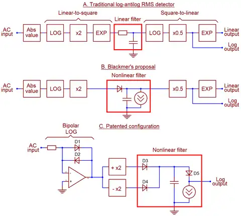
Contemporary electronic RMS detectors had "normal", linear outputs, and were built exactly following the definition of RMS. The detector would compute square of the input signal, time-average the square using a low-pass filter or an integrator, and then compute square root of that average to produce linear, not logarithmic, output. Analog computation of squares and square roots was performed using either expensive variable-transconductance analog multipliers (which remain expensive in the 21st century[7]) or simpler and cheaper logarithmic converters employing exponential current-voltage characteristic of a bipolar transistor.[1] Thermal RMS conversion was too slow for audio purposes; electronic RMS detectors worked fine in measurement instruments, but their dynamic range was too narrow for professional audio - precisely because they operated on squares of input signal, taking up twice its dynamic range.[1][7]
Blackmer reasoned that the log-antilog detector may be simplified by taking up processing to log domain, omitting physical squaring of input signals and thus retaining its full dynamic range.[3] Squaring and taking square roots in log domain is very cheap, being simple scaling by a factor of 2 or 1/2.[7] However, simple linear filters do not work in log domain, producing incorrect, irrelevant output. Correct time-averaging required nonlinear filters of yet unknown topology. Blackmer proposed simple replacement of a resistor in RC network with a silicon diode biased with a fixed idle current. Since small-signal impedance of such diode is controlled linearly by current, changing this current controls settling time of the detector.[3] Cutoff frequency of this first order filter equals
- ,[5]
where is thermal voltage (hence the frequency shifts with temperature). The equation is valid for a range of idle currents over 60 dB, allowing wide tuning opportunity.[4][8] The circuit has fast attack and slow decay, which are locked to each other and cannot be adjusted separately.[9] Logarithmic output voltage is proportional to the mean of the square at a rate of around 3 mV/dB, and proportional to RMS at around 6 mV/dB.[9]
When the crude test circuit was built, Blackmer and his associates did not expect it to work as a true RMS detector, but it did. According to Robert Adams, it "seemed to behave ideally",[4] and rigorous tests with various waveforms confirmed ideal RMS performance. The circuit was absolutely insensitive to phase shifts in input signal. It was immediately patented and employed in dbx, Inc. professional audio processors. No one in the company, including Blackmer, could explain why it works at all until 1977, when Robert Adams began work on proper mathematical proof of RMS compliance.[4] Adams tried to extend log-domain concept to Sallen–Key topology and failed.[4] He published his thesis in 1979, and was later credited as the inventor of log-domain filter concept,[10] but the idea remained unknown to general public until the 1993 pioneering work by Douglas Frey.[11][2]
References
- Adams 2006, p. xii.
- Roberts & Leung 2006, p. 11.
- Adams 2006, p. xiii.
- Adams 2006, p. xiv.
- Roberts & Leung 2006, p. 10.
- Adams 2006, p. xi.
- Tyler & Kirkwood 2008, p. 346.
- Roberts & Leung 2006, p. xv.
- Tyler & Kirkwood 2008, p. 348.
- Roberts & Leung 2006, p. 6.
- Adams 2006, p. xv.
Bibliography
- Adams, Robert (2006). "Foreword". In Gordon W. Roberts, Vincent W. Leung (ed.). Design and Analysis of Integrator-Based Log-Domain Filter Circuits. Springer Science & Business Media. ISBN 9780306470547.
- Roberts, Gordon; Leung, Vincent (2006). Gordon W. Roberts, Vincent W. Leung (ed.). Design and Analysis of Integrator-Based Log-Domain Filter Circuits. Springer Science & Business Media. ISBN 9780306470547.
- Tyler, Les; Kirkwood, Wayne (2008). "12.3.4 Dedicated Analog Integrated Circuits for Audio Applications". In Glen Ballou (ed.). Handbook for Sound Engineers. Fourth Edition. Focal/Elsevier. ISBN 978-0-240-80969-4.
