Pulse-forming network
A pulse-forming network (PFN) is an electric circuit that accumulates electrical energy over a comparatively long time, and then releases the stored energy in the form of a relatively square pulse of comparatively brief duration for various pulsed power applications. In a PFN, energy storage components such as capacitors, inductors or transmission lines are charged by means of a high-voltage power source, then rapidly discharged into a load through a high-voltage switch, such as a spark gap or hydrogen thyratron. Repetition rates range from single pulses to about 104 per second. PFNs are used to produce uniform electrical pulses of short duration to power devices such as klystron or magnetron tube oscillators in radar sets, pulsed lasers, particle accelerators, flashtubes, and high-voltage utility test equipment.


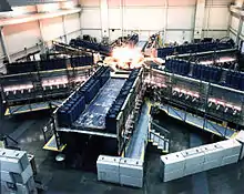
Much high-energy research equipment is operated in a pulsed mode, both to keep heat dissipation down and because high-energy physics often occurs at short time scales, so large PFNs are widely used in high-energy research. They have been used to produce nanosecond-length pulses with voltages of up to 106–107 volts and currents up to 106 amperes, with peak power in the terawatt range, similar to lightning bolts.
Implementation
A PFN consists of a series of high-voltage energy-storage capacitors and inductors. These components are interconnected as a "ladder network" that behaves similarly to a length of transmission line. For this reason, a PFN is sometimes called an "artificial, or synthetic, transmission line". Electrical energy is initially stored within the charged capacitors of the PFN by a high-voltage DC power supply. When the PFN is discharged, the capacitors discharge in sequence, producing an approximately rectangular pulse. The pulse is conducted to the load through a transmission line. The PFN must be impedance-matched to the load to prevent the energy reflecting back toward the PFN.
Transmission-line PFNs

A length of transmission line can be used as a pulse-forming network.[1][2] This can give substantially flat-topped pulses at the inconvenience of using of a large length of cable.
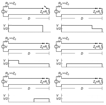
In a simple charged transmission-line pulse generator (animation, right) a length of transmission line such as a coaxial cable is connected through a switch to a matched load RL at one end, and at the other end to a DC voltage source V through a resistor RS, which is large compared to the characteristic impedance Z0 of the line.[1] When the power supply is connected, it slowly charges up the capacitance of the line through RS. When the switch is closed, a voltage equal to V/2 is applied to the load, the charge stored in the line begins to discharge through the load with a current of V/2Z0, and a voltage step travels up the line toward the source.[2] The source end of the line is approximately an open circuit due to the high RS,[1] so the step is reflected uninverted and travels back down the line toward the load. The result is that a pulse of voltage is applied to the load with a duration equal to 2D/c, where D is the length of the line, and c is the propagation velocity of the pulse in the line.[1] The propagation velocity in typical transmission lines is generally more than 50% of the speed of light. For example, in most types of coaxial cable the propagation velocity is approximately 2/3 the speed of light, or 20 cm/ns.
High-power PFNs generally use specialized transmission lines consisting of pipes filled with oil or deionized water as a dielectric to handle the high power stress.[2]
A disadvantage of simple PFN pulse generators is that because the transmission line must be matched to the load resistance RL to prevent reflections, the voltage stored on the line is divided equally between the load resistance and the characteristic impedance of the line, so the voltage pulse applied to the load is only one-half the power-supply voltage.[1][2]
Blumlein transmission line

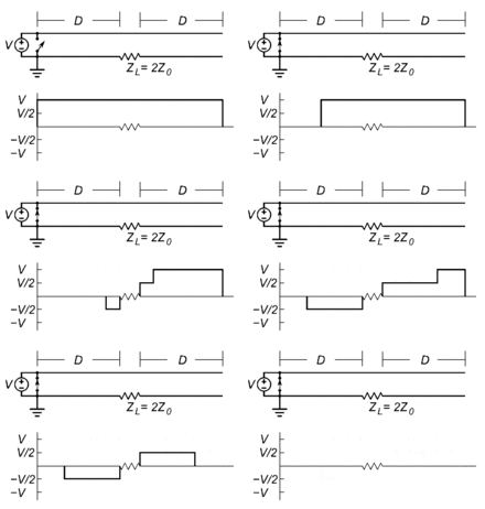
A transmission line circuit which circumvented the above problem, producing an output pulse equal to the power-supply voltage V, was invented in 1937 by British engineer Alan Blumlein[3] and is widely used today in PFNs.[1] In the Blumlein generator (animation, right), the load is connected in series between two equal-length transmission lines, which are charged by a DC power supply at one end (note that the right line is charged through the impedance of the load).[1] To trigger the pulse, a switch short-circuits the line at the power-supply end, causing a negative voltage step to travel toward the load. Since the characteristic impedance Z0 of the line is made equal to half the load impedance RL, the voltage step is half-reflected and half-transmitted,[1] resulting in two symmetrical opposite-polarity voltage steps, which propagate away from the load, creating between them a voltage drop of V/2 − (−V/2)= V across the load. The voltage steps reflect from the ends and return, ending the pulse. As in other charge-line generators, the pulse duration is equal to 2D/c, where D is the length of the individual transmission lines.[1] A second advantage of the Blumlein geometry is that the switching device can be grounded, rather than located in the high-voltage side of the transmission line as in the typical charged line, which complicates the triggering electronics.
Uses of PFNs
Upon command, a high-voltage switch transfers the energy stored within the PFN into the load. When the switch "fires" (closes), the network of capacitors and inductors within the PFN creates an approximately square output pulse of short duration and high power. This high-power pulse becomes a brief source of high power to the load.
Sometimes a specially designed pulse transformer is connected between the PFN and load. This technique improves the impedance match between the PFN and the load so as to improve power-transfer efficiency. A pulse transformer is typically required when driving higher-impedance devices such as klystrons or magnetrons from a PFN. Because the PFN is charged over a relatively long time and then discharged over a very short time, the output pulse may have a peak power of megawatts or even terawatts.
The combination of a high-voltage source, PFN, HV switch, and pulse transformer (when required) is sometimes called a "power modulator" or "pulser".
See also
References
- Haddad, A.; D. F. Warne (2004). Advances in High Voltage Engineering. IET. pp. 600–603. ISBN 0852961588.
- Mesyats, Gennady A. (2005). Pulsed Power. Springer. pp. 13–14, 125. ISBN 0306486547.
- UK Patent 589127, Improvements in or relating to apparatus for generating electrical impulses, Alan Dower Blumlein, filed October 10, 1941, granted June 12, 1947.
External links
- Eric Heine, "Conversion". NIKHEF Electronic Department, Amsterdam, the Netherlands.
- Riepe, Kenneth B., "High-voltage microsecond pulse-forming network". Review of Scientific Instruments Vol 48(8) pp. 1028–1030. August 1977. (Abstract)
- Glasoe, G. Norris, Lebacqz, Jean V., "Pulse Generators", McGraw-Hill, MIT Radiation Laboratory Series, Volume 5, 1948.