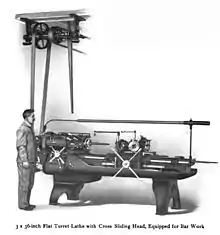
Turret lathe
A turret lathe is a form of metalworking lathe that is used for repetitive production of duplicate parts, which by the nature of their cutting process are usually interchangeable. It evolved from earlier lathes with the addition of the turret, which is an indexable toolholder that allows multiple cutting operations to be performed, each with a different cutting tool, in easy, rapid succession, with no need for the operator to perform set-up tasks in between (such as installing or uninstalling tools) or to control the toolpath. The latter is due to the toolpath's being controlled by the machine, either in jig-like fashion, via the mechanical limits placed on it by the turret's slide and stops, or via digitally-directed servomechanisms for computer numerical control lathes.
The name derives from the way early turrets took the general form of a flattened cylindrical block mounted to the lathe's cross-slide, capable of rotating about the vertical axis and with toolholders projecting out to all sides, and thus vaguely resembled a swiveling gun turret.
Capstan lathe is the usual name in the UK and Commonwealth, though the two terms are also used in contrast: see below, Capstan versus turret.
History

Turret lathes became indispensable to the production of interchangeable parts and for mass production.
The first turret lathe was built by Stephen Fitch in 1845 to manufacture screws for pistol percussion parts.[2] In the mid-nineteenth century, the need for interchangeable parts for Colt revolvers enhanced the role of turret lathes in achieving this goal as part of the "American system" of manufacturing arms. Clock-making and bicycle manufacturing had similar requirements.[3] Christopher Spencer invented the first fully automated turret lathe in 1873, which led to designs using cam action or hydraulic mechanisms.[2]
From the late-19th through mid-20th centuries, turret lathes, both manual and automatic (i.e., screw machines and chuckers), were one of the most important classes of machine tools for mass production. They were used extensively in the mass production for the war effort in World War II.[4]
Types
There are many variants of the turret lathe. They can be most generally classified by size (small, medium, or large); method of control (manual, automated mechanically, or automated via computer (numerical control (NC) or computer numerical control (CNC)); and bed orientation (horizontal or vertical).
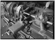
Archetypical: horizontal, manual
In the late 1830s a "capstan lathe" with a turret was patented in Britain.[5] The first American turret lathe was invented by Stephen Fitch in 1845.[6] The archetypical turret lathe, and the first in order of historical appearance, is the horizontal-bed, manual turret lathe. The term "turret lathe" without further qualification is still understood to refer to this type. The formative decades for this class of machine were the 1840s through 1860s, when the basic idea of mounting an indexable turret on a bench lathe or engine lathe was born, developed, and disseminated from the originating shops to many other factories. Some important tool-builders in this development were Stephen Fitch; Gay, Silver & Co.; Elisha K. Root of Colt; J.D. Alvord of the Sharps Armory; Frederick W. Howe, Richard S. Lawrence, and Henry D. Stone of Robbins & Lawrence; J.R. Brown of Brown & Sharpe; and Francis A. Pratt of Pratt & Whitney.[7] Various designers at these and other firms later made further refinements.
Semi-automatic

Sometimes machines similar to those above, but with power feeds and automatic turret-indexing at the end of the return stroke, are called "semi-automatic turret lathes". This nomenclature distinction is blurry and not consistently observed. The term "turret lathe" encompasses them all. During the 1860s, when semi-automatic turret lathes were developed,[6] they were sometimes called "automatic". What we today would call "automatics", that is, fully automatic machines, had not been developed yet. During that era both manual and semi-automatic turret lathes were sometimes called "screw machines", although we today reserve that term for fully automatic machines.[8]
Automatic
During the 1870s through 1890s, the mechanically automated "automatic" turret lathe was developed and disseminated. These machines can execute many part-cutting cycles without human intervention. Thus the duties of the operator, which were already greatly reduced by the manual turret lathe, were even further reduced, and productivity increased. These machines use cams to automate the sliding and indexing of the turret and the opening and closing of the chuck. Thus, they execute the part-cutting cycle somewhat analogously to the way in which an elaborate cuckoo clock performs an automated theater show. Small- to medium-sized automatic turret lathes are usually called "screw machines" or "automatic screw machines", while larger ones are usually called "automatic chucking lathes", "automatic chuckers", or "chuckers".
Machine tools of the "automatic" variety, which in the pre-computer era meant mechanically automated, had already reached a highly advanced state by World War I.
Computer numerical control
When World War II ended, the digital computer was poised to develop from a colossal laboratory curiosity into a practical technology that could begin to disseminate into business and industry. The advent of computer-based automation in machine tools via numerical control (NC) and then computer numerical control (CNC) displaced to a large extent, but not at all completely, the previously existing manual and mechanically automated machines.
Numerically controlled turrets allow automated selection of tools on a turret.[9] CNC lathes may be horizontal or vertical in orientation and mount six separate tools on one or more turrets.[10] Such machine tools can work in two axes per turret, with up to six axes being feasible for complex work.[10]
Vertical
Vertical turret lathes have the workpiece held vertically, which allows the headstock to sit on the floor and the faceplate to become a horizontal rotating table, analogous to a huge potter's wheel. This is useful for the handling of very large, heavy, short workpieces. Vertical lathes in general are also called "vertical boring mills" or often simply "boring mills"; therefore a vertical turret lathe is a vertical boring mill equipped with a turret.[9]
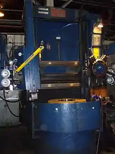 CNC VTL, 46" (1168 mm) Bullard High Column Dynatrol, built mid-1960s.
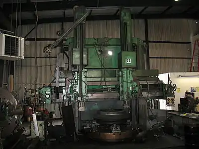 CNC VTL, 88" (2235 mm) Niles Vertical Turret Lathe, built mid-1950s
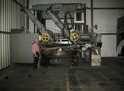 CNC VTL, King Vertical Turret Lathe Model 100, built 1955
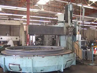 CNC VTL, 16' Rockford Open Side, built 1980
Other variations
Capstan versus turret

The term "capstan lathe" overlaps in sense with the term "turret lathe" to a large extent. In many times and places, it has been understood to be synonymous with "turret lathe". In other times and places it has been held in technical contradistinction to "turret lathe", with the difference being in whether the turret's slide is fixed to the bed (ram-type turret) or slides on the bed's ways (saddle-type turret).[11][12] The difference in terminology is mostly a matter of United Kingdom and Commonwealth usage versus United States usage.[7]
Flat
A subtype of horizontal turret lathe is the flat-turret lathe. Its turret is flat (and analogous to a rotary table), allowing the turret to pass beneath the part. Patented by James Hartness of Jones & Lamson, and first disseminated in the 1890s, it was developed to provide more rigidity via requiring less overhang in the tool setup, especially when the part is relatively long.[13]
Hollow-hexagon
Hollow-hexagon turret lathes competed with flat-turret lathes by taking the conventional hexagon turret and making it hollow, allowing the part to pass into it during the cut, analogously to how the part would pass over the flat turret. In both cases, the main idea is to increase rigidity by allowing a relatively long part to be turned without the tool overhang that would be needed with a conventional turret, which is not flat or hollow.[14]
Monitor lathe
The term "monitor lathe" formerly (1860s-1940s) referred to the class of small- to medium-sized manual turret lathes used on relatively small work. The name was inspired by the monitor-class warships, which the monitor lathe's turret resembled. Today, lathes of such appearance, such as the Hardinge DSM-59 and its many clones, are still common, but the name "monitor lathe" is no longer current in the industry.[8]
Toolpost turrets and tailstock turrets
Turrets can be added to non-turret lathes (bench lathes, engine lathes, toolroom lathes, etc.) by mounting them on the toolpost, tailstock, or both. Often these turrets are not as large as a turret lathe's, and they usually do not offer the sliding and stopping that a turret lathe's turret does; but they do offer the ability to index through successive tool settings.
Example of a part-cutting cycle
By pushing the hand lever of a manual turret forward, the tool is moved via the turret's slide toward the workpiece being held by the chuck, soon making contact and cutting or forming the part. On the return stroke, the tool is retracted and then indexed to the next tool held in the turret. In this way, a sequence of operations can be performed on a part without switching tools with each operation. That is, different tools can be shifted into position without the need to unscrew one and screw in another. Each tool can be set for a different length of travel by a stop screw located at the far right of the turret.
As an example, if one wanted to make a batch of special knurled-head screws, the turret could be set up with tools and used in this sequence:
- Stop to set length of bar stock to be machined;
- Box tool to turn diameter of stock down to threading size;
- Geometric die head to cut external threads on turned-down part,
- Knurling tool to knurl the screw's head.
After this, a front tool on the cross slide could cut a groove in the knurled area, providing a chamfer, and then a rear tool would be brought forward to cut the finished screw from the bar, called "parting it off".
Threading on a Manual Lathe
An example of a process performed on a manual lathe is threading. Threading is a process that produces a helical ridge on the exterior of a round, machined part. The threads are cut by slowing down the speed of the spindle to 1/4 The tool that is used when threading is a sharp, 60 degree cutting tool. Threading follows a specific chart which can be located very easily on any machine. The steps to set up a machine for threading include:
- Setting the spindle speed to 1/4 of normal cutting speed for that material.
- Set the machine's quick change gearbox that matches the desired pitch.
- For right-handed threads, the compound rest needs to be set at 29 degrees.
- Set the 60 degree tool to the lathe center.
- Use layout solution to see changes in work easier then as you are cutting, use the cross feed to cut the threads in .025" roughing increments.
- When finishing, be careful not to run the cross feed too far in, or the threads will become too brittle and unreliable.
When threading, a tool as sharp as a threading tool can break very easily and become fragile. Make sure that tools are used correctly and safely. A lathe can also be used to help with a tap and die process to add interior and exterior threads. To start the process, the tailstock of the lathe is used to line the tap or die handle up with the thread area on the part. As you turn the tap handle, use the tailstock to keep a good pressure on the tap or die.
References
- Hartness 1910.
- Zhang, Ce; Yang, Jianming (2020-01-03). A History of Mechanical Engineering. Springer Nature. pp. 128, 177–9, 429. ISBN 978-981-15-0833-2.
- Hounshell, David (1985). From the American System to Mass Production, 1800-1932: The Development of Manufacturing Technology in the United States. JHU Press. pp. 48–50. ISBN 978-0-8018-3158-4.
- Parker, Dana T. Building Victory: Aircraft Manufacturing in the Los Angeles Area in World War II, p. 81, 123, Cypress, CA, 2013. ISBN 978-0-9897906-0-4.
- Editors (1924). American Machinist. McGraw-Hill. p. 273.
{{cite book}}:|last=has generic name (help) - Crosher, William P. (2014). A Gear Chronology. Bloomington, Indiana: Xlibris. p. 144. ISBN 978-1499071146.
- Rolt 1965, p. 165.
- Editors (1901). "Part 5: Lathe Work". Reading working drawings. Arithmetic. Measuring instruments. Lathe work. Colliery Engineer Company. pp. 3–11.
{{cite book}}:|last=has generic name (help) - Bawa, H. S. (2004). Manufacturing processes. Vol. 1. New Delhi: Tata McGraw-Hill. p. 57. ISBN 0-07-053525-6. OCLC 57660758.
- Smid, Peter (2003). CNC programming handbook : a comprehensive guide to practical CNC programming (2nd ed.). New York: Industrial Press. pp. 11–14. ISBN 0-8311-3158-6. OCLC 52364066.
- Capstan and Turret differences
- H.W. Ward & Co., Ltd 1938.
- Roe 1937, pp. 34–36.
- Editors (1921). A.S.M.E. Mechanical Catalog and Directory. American Society of Mechanical Engineers. p. 456.
{{cite book}}:|last=has generic name (help)
Bibliography
- Hartness, James (1910), Hartness Flat Turret Lathe Manual, Springfield, Vermont: Jones and Lamson Machine Company, ISBN 9780282208783, retrieved 26 February 2016.
- Hounshell, David A. (1984), From the American System to Mass Production, 1800–1932: The Development of Manufacturing Technology in the United States, Baltimore, Maryland: Johns Hopkins University Press, ISBN 978-0-8018-2975-8, LCCN 83016269, OCLC 1104810110
- H.W. Ward & Co., Ltd (1938), Operators' Hand-book (4th ed.), Dale Road, Bournbrook, Birmingham, England: H.W. Ward & Co., Ltd.
- Roe, Joseph Wickham (1937), James Hartness: A Representative of the Machine Age at Its Best, New York: American Society of Mechanical Engineers, LCCN 37016470, OCLC 3456642. link from HathiTrust.
- Rolt, L. T. C. (1965), A Short History of Machine Tools, Cambridge, Massachusetts, USA: MIT Press, OCLC 250074. Co-edition published as Rolt, L. T. C. (1965), Tools for the Job: a Short History of Machine Tools, London: B. T. Batsford, LCCN 65080822.
External links
- Example cycle on a manual turret lathe, narrated by operator from YouTube
- Movement of the turrets and the taking of various cuts on a CNC vertical turret lathe from YouTube
- Movement of the turret and the taking of various cuts on a manual engine lathe retrofitted with a CNC turret from YouTube
