Circulator
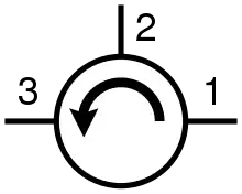
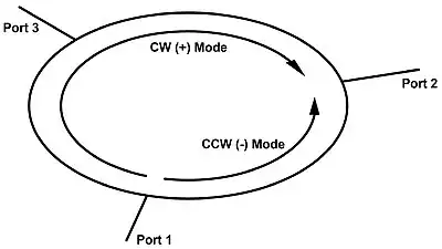
In electrical engineering, a circulator is a passive, non-reciprocal three- or four-port device that only allows a microwave or radio-frequency (RF) signal to exit through the port directly after the one it entered. Optical circulators have similar behavior. Ports are where an external waveguide or transmission line, such as a microstrip line or a coaxial cable, connects to the device. For a three-port circulator, a signal applied to port 1 only comes out of port 2; a signal applied to port 2 only comes out of port 3; a signal applied to port 3 only comes out of port 1, and so on. An ideal three-port circulator has the following scattering matrix:

Types
Depending on the materials involved, circulators fall into two main categories: ferrite circulators and non-ferrite circulators.
Ferrite
Ferrite circulators are radio-frequency circulators which employ magnetized microwave ferrite materials. They fall into two main classes: differential phase shift circulators and junction circulators, both of which are based on cancellation of waves propagating over two different paths in or near magnetized ferrite material. Waveguide circulators may be of either type, while more compact devices based on stripline are usually of the junction type.[1] [2] Two or more junction circulators can be combined in a single component to give four or more ports. Typically permanent magnets produce a static magnetic bias in the microwave ferrite material. Ferrimagnetic garnet crystal is used in optical circulators.
Theory of operation
For operation, ferrite circulators rely on the unique anisotropic and non-reciprocal properties of magnetized microwave ferrite material.[3] Microwave electromagnetic waves propagating in magnetized ferrite interact with electron spins in the ferrite and are consequently influenced by the microwave magnetic permeability of the ferrite. This permeability is mathematically described by a linear vector operator, also known as a tensor. In the case of magnetized ferrite, the permeability tensor is the Polder tensor. The permeability is a function of the direction of microwave propagation relative to the direction of static magnetization of the ferrite material. Hence, microwave signals propagating in different directions in the ferrite experience different magnetic permeabilities.
In the CGS system, the Polder tensor[4] is

where (neglecting damping)


MHz / Oe is the effective gyromagnetic ratio and , the so-called effective g-factor, is a ferrite material constant typically in the range of 1.5 - 2.6, depending on the particular ferrite material. is the frequency of the RF/microwave signal propagating through the ferrite, is the internal magnetic bias field, and is the magnetization of the ferrite material.


In junction circulators and differential phase shift circulators, microwave signal propagation is usually orthogonal to the static magnetic bias field in the ferrite. This is the so-called transverse field case. The microwave propagation constants for this case, neglecting losses are[5]


where is the Permeability of Free Space and is the Absolute permittivity of the ferrite material. In a circulator, these propagation constants describe waves having Elliptical polarization that would propagate in the direction of the static magnetic bias field, which is through the thickness of the ferrite. The plus and minus subscripts of the propagation constants indicate opposite wave polarizations.


Stripline junction circulators
A stripline junction circulator contains a resonator, which is located at the central junction of the striplines. This resonator may have any shape that has three-fold Rotational symmetry, such as a disk, hexagon, or triangle. An RF/microwave signal entering a circulator port is connected via a stripline to the resonator, where energy is coupled into two counter-rotating circular modes formed by the elliptically polarized waves. These circular modes have different phase velocities which can cause them to combine constructively or destructively at a given port. This produces an anti-node at one port (port 2 if the signal is incident upon port 1) and a node or null at another port (port 3 if the microwave energy is coupled from port 1 to port 2 and not reflected back into port 2).
If losses are neglected for simplification, the counter-rotating modes must differ in phase by an integer multiple of for signal propagation from port 1 to port 2 (or from port 2 to port 3, or from port 3 to port 1)[6]:


and similarly, for the remaining port (port 3 if signal propagation is from port 1 to port 2) to be nulled,

where is the path length between adjacent ports and and are integers. Solving the two preceding equations simultaneously, for proper circulation we must have


and

Junction type stripline circulators utilize two ferrite disks above and below the stripline. These ferrites are circularly magnetized in opposite directions. They form two separate resonators with the stripline disk between them. The static magnetic bias alters the effective permeabilities in the top and bottom ferrites. The ferrite whose circular magnetization is in the same direction as the resultant electron spin precession, will see a permeability increase. The ferrite that is magnetized opposite the electron spin precession will see a permeability decrease. These changing permeabilities result in resonant frequency shifts of the two resonators previously mentioned. The operating frequency is set between the two resonances such that the impedance angle of both resonators is set to 30 degrees (for a three port implementation). The ferrite with the higher permeability will have a higher resonance frequency and an inductive reactance component. The lower permeability ferrite has a lower resonance and capacitive reactance component.[2] These circulator types operate based on faraday rotation. Wave cancellation occurs when waves propagate with and against the circulation direction. An incident wave arriving at any port is split equally into two waves. They propagate in each direction around the circulator with different phase velocities. When they arrive at the output port they have different phase relationships and thus combine accordingly. This combination of waves propagating at different phase velocities is how junction circulators fundamentally operate.
Though ferrite circulators can provide good "forward" signal circulation while suppressing greatly the "reverse" circulation, their major shortcomings, especially at low frequencies, are the bulky sizes and the narrow bandwidths.
- Internal Construction of Stripline Junction Circulators
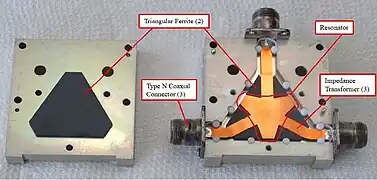 Internal construction of a stripline junction circulator having triangular ferrites and an irregular triangle-shaped resonator.
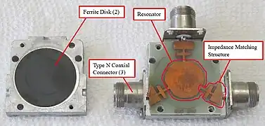 Internal construction of stripline junction circulator having disk ferrites and a disk-shaped resonator.
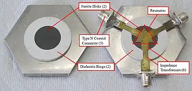 Internal construction of a stripline junction circulator having disk ferrites and a triangle-shaped resonator.
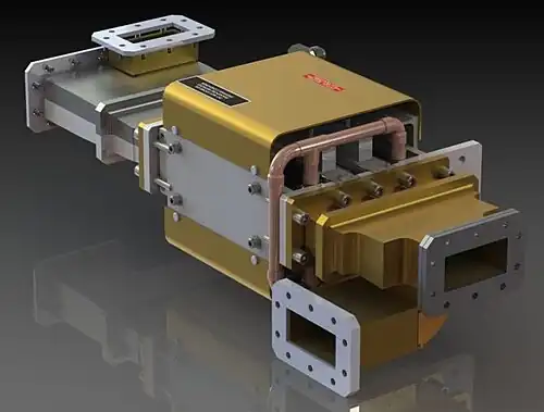
Waveguide junction circulators

Differential Phase Shift Circulators
Non-ferrite
Early work on non-ferrite circulators includes active circulators using transistors that are non-reciprocal in nature.[7] In contrast to ferrite circulators which are passive devices, active circulators require power. Major issues associated with transistor-based active circulators are the power limitation and the signal-to-noise degradation,[8] which are critical when it is used as a duplexer for sustaining the strong transmit power and clean reception of the signal from the antenna.
Varactors offer one solution. One study employed a structure similar to a time-varying transmission line with the effective nonreciprocity triggered by a one-direction propagating carrier pump.[9] This is like an AC-powered active circulator. The research claimed to be able to achieve positive gain and low noise for receiving path and broadband nonreciprocity. Another study used resonance with nonreciprocity triggered by angular-momentum biasing, which more closely mimics the way that signals passively circulate in a ferrite circulator.[10]
In 1964, Mohr presented and experimentally demonstrated a circulator based on transmission lines and switches.[11] In April, 2016 a research team significantly extended this concept, presenting an integrated circuit circulator based on N-path filter concepts.[12][13] It offers the potential for full-duplex communication (transmitting and receiving at the same time with a single shared antenna over a single frequency). The device uses capacitors and a clock and is much smaller than conventional devices.[14]
Applications
Isolator
When one port of a three-port circulator is terminated in a matched load, it can be used as an isolator, since a signal can travel in only one direction between the remaining ports.[15] An isolator is used to shield equipment on its input side from the effects of conditions on its output side; for example, to prevent a microwave source being detuned by a mismatched load.
Duplexer
In radar, circulators are used as a type of duplexer, to route signals from the transmitter to the antenna and from the antenna to the receiver, without allowing signals to pass directly from transmitter to receiver. The alternative type of duplexer is a transmit-receive switch (TR switch) that alternates between connecting the antenna to the transmitter and to the receiver. The use of chirped pulses and a high dynamic range may lead to temporal overlap of the sent and received pulses, however, requiring a circulator for this function.
Reflection amplifier
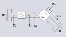
A reflection amplifier is a type of microwave amplifier circuit utilizing negative differential resistance diodes such as tunnel diodes and Gunn diodes. Negative differential resistance diodes can amplify signals, and often perform better at microwave frequencies than two-port devices. However, since the diode is a one-port (two terminal) device, a nonreciprocal component is needed to separate the outgoing amplified signal from the incoming input signal. By using a 3-port circulator with the signal input connected to one port, the biased diode connected to a second, and the output load connected to the third, the output and input can be uncoupled.
References
- Bosma, H. (1964-01-01). "On Stripline Y-Circulation at UHF". IEEE Transactions on Microwave Theory and Techniques. 12 (1): 61–72. Bibcode:1964ITMTT..12...61B. doi:10.1109/TMTT.1964.1125753. ISSN 0018-9480.
- Fay, C.E.; Comstock, R.L. (1965-01-01). "Operation of the Ferrite Junction Circulator". IEEE Transactions on Microwave Theory and Techniques. 13 (1): 15–27. Bibcode:1965ITMTT..13...15F. doi:10.1109/TMTT.1965.1125923. ISSN 0018-9480. S2CID 111367080.
- Harris, Vincent G. (2023). Modern Ferrites, Volume 2: Emerging Technologies and Applications. Wiley-IEEE Press. ISBN 978-1-394-15613-9.
- Polder, D (1949). "On the Theory of Ferromagnetic Resonance". The London, Edinburgh, and Dublin Philosophical Magazine and Journal of Science. 40 (300): 99–115. doi:10.1080/14786444908561215.
- Linkhart, Douglas K. (2014). Microwave Circulator Design, Second Edition. Artech House. ISBN 978-1-60807-583-6.
- Soohoo, Ronald F. (1985). Microwave Magnetics. Harper & Row. ISBN 0-06-046367-8.
- Tanaka, S.; Shimomura, N.; Ohtake, K. (1965-03-01). "Active circulators - The realization of circulators using transistors". Proceedings of the IEEE. 53 (3): 260–267. doi:10.1109/PROC.1965.3683. ISSN 0018-9219.
- Carchon, G.; Nanwelaers, B. (2000-02-01). "Power and noise limitations of active circulators". IEEE Transactions on Microwave Theory and Techniques. 48 (2): 316–319. Bibcode:2000ITMTT..48..316C. doi:10.1109/22.821785. ISSN 0018-9480.
- Qin, Shihan; Xu, Qiang; Wang, Y.E. (2014-10-01). "Nonreciprocal Components With Distributedly Modulated Capacitors". IEEE Transactions on Microwave Theory and Techniques. 62 (10): 2260–2272. Bibcode:2014ITMTT..62.2260Q. doi:10.1109/TMTT.2014.2347935. ISSN 0018-9480. S2CID 13987504.
- Estep, N. A.; Sounas, D. L.; Alù, A. (2016-02-01). "Magnetless Microwave Circulators Based on Spatiotemporally Modulated Rings of Coupled Resonators". IEEE Transactions on Microwave Theory and Techniques. 64 (2): 502–518. doi:10.1109/TMTT.2015.2511737. ISSN 0018-9480. S2CID 17421796.
- Mohr, Richard (1964). "A New Nonreciprocal Transmission Line Device". Proceedings of the IEEE. 52 (5): 612. doi:10.1109/PROC.1964.3007.
- Nordrum, Amy (2016-04-15). "New Full Duplex Radio Chip Transmits and Receives Wireless Signals at Once". IEEE Spectrum: Technology, Engineering, and Science News. Retrieved 2016-07-22.
- Reiskarimian, Negar; Krishnaswamy, Harish (2016-04-15). "Magnetic-free non-reciprocity based on staggered commutation". Nature Communications. 7: 11217. Bibcode:2016NatCo...711217R. doi:10.1038/ncomms11217. PMC 4835534. PMID 27079524.
- Wang, Brian (April 18, 2016). "Next Big Future: Novel miniaturized circulator opens way to doubling wireless capacity". nextbigfuture.com. Retrieved 2016-04-19.
- For a description of a circulator, see Jachowski (1976)
Further reading
- Chait, H. N.; Curry, T. R. (1959), "Y-Circulator", Journal of Applied Physics, 30 (4): S152–S153, Bibcode:1959JAP....30S.152C, doi:10.1063/1.2185863
- US 3935549, Jachowski, Ronald E., "Ferrite Circulator", published 1976-01-27
- Linkhart, Douglas K. (2014), Microwave Circulator Design (Second ed.), Artech House, ISBN 978-1608075836
- Ohm, E. A. (1956), "A Broad-Band Microwave Circulator", IRE Transactions on Microwave Theory and Techniques, 4 (4): 210–217, Bibcode:1956ITMTT...4..210O, doi:10.1109/TMTT.1956.1125064
- Wenzel, C. (July 1991), "Low Frequency Circulator/Isolator Uses No Ferrite or Magnet" (PDF), RF Design, archived (PDF) from the original on 2022-10-09
External links
- Circulators and Isolators
- RF Circulators what they are, different types, how they work, etc.