Composite video
Composite video is an analog video format that typically carries a 525 or 625 line signal on a single channel, unlike the higher-quality S-Video (two channels) and the even higher-quality component video (three or more channels).
 On consumer products a yellow RCA connector is typically used for composite video. | |||
| Type | Analog video connector | ||
|---|---|---|---|
| Production history | |||
| Designed | 1954[1]–1956[2] | ||
| General specifications | |||
| Length | Maximum of 50 m | ||
| External | Yes | ||
| Video signal | NTSC, PAL or SECAM video | ||
| Pins | 1 plus grounding shield | ||
| Connector | RCA connector | ||
| Electrical | |||
| Signal | 1 volt[3] | ||
| Pinout | |||
| Pin 1 | center | video | |
| Pin 2 | sheath | ground | |
A yellow RCA connector is typically used for composite video, with the audio being carried on separate additional L/R RCA connectors. In professional settings, or on devices that are too small for an RCA connector, such as a digital camera, other types of connectors can be used.
Composite video is also known by the initials CVBS for Composite Video Baseband Signal or Color, Video, Blanking and Sync,[4][5] or is simply referred to as SD video for the standard-definition television signal it conveys.
There are three dominant variants of composite video signals, corresponding to the analog color system used (NTSC, PAL, and SECAM), but purely monochrome signals can also be used.
Signal components


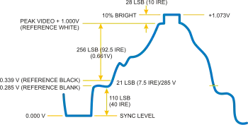
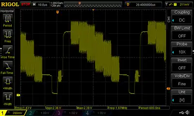
A composite video signal combines, on one wire, the video information required to recreate a color picture, as well as line and frame synchronization pulses. The color video signal is a linear combination of the luminance () of the picture and a modulated subcarrier which carries the chrominance or color information (), a combination of hue and saturation. Details of the combining process vary between the NTSC, PAL and SECAM systems.
The frequency spectrum of the modulated color signal overlaps that of the baseband signal, and separation relies on the fact that frequency components of the baseband signal tend to be near harmonics of the horizontal scanning rate, while the color carrier is selected to be an odd multiple of half the horizontal scanning rate; this produces a modulated color signal that consists mainly of harmonic frequencies that fall between the harmonics in the baseband luma signal, rather than both being in separate continuous frequency bands alongside each other in the frequency domain. The signals may be separated using a comb filter.[6] In other words, the combination of luma and chrominance is indeed a frequency-division technique, but it is much more complex than typical frequency-division multiplexing systems like the one used to multiplex analog radio stations on both the AM and FM bands.
A gated and filtered signal derived from the color subcarrier, called the burst or colorburst, is added to the horizontal blanking interval of each line (excluding lines in the vertical sync interval) as a synchronizing signal and amplitude reference for the chrominance signals. In NTSC composite video, the burst signal is inverted in phase (180° out of phase) from the reference subcarrier.[7] In PAL, the phase of the color subcarrier alternates on successive lines. In SECAM, no colorburst is used since phase information is irrelevant.
Composite artifacts

The combining of component signals to form the composite signal does the same, causing a checkerboard video artifact known as dot crawl. Dot crawl is a defect that results from crosstalk due to the intermodulation of the chrominance and luminance components of the signal. This is usually seen when chrominance is transmitted with high bandwidth, and its spectrum reaches into the band of the luminance frequencies. Comb filters are commonly used to separate signals and eliminate these artifacts from composite sources. S-Video and component video avoid this problem as they maintain the component signals separately.
Recording
Most home analog video equipment record a signal in (roughly) composite format: LaserDiscs store a true composite signal, while consumer videotape formats (including VHS and Betamax) and commercial and industrial tape formats (including U-matic) use modified composite signals (generally known as color-under).[8] The professional D-2 videocassette format digitally records and reproduces composite video signals using PCM encoding of the analog signal on the magnetic tape.
Extensions
A number of so-called extensions to the visible TV image can be transmitted using composite video. Since TV screens hide the vertical blanking interval of a composite video signal, these take advantage of the unseen parts of the signal. Examples of extensions include teletext, closed captioning, information regarding the show title, a set of reference colors that allows TV sets to automatically correct NTSC hue maladjustments, widescreen signaling (WSS) for switching between 4:3 and 16:9 display formats, etc.
Connectors and cable

In home applications, the composite video signal is typically connected using an RCA connector, normally yellow. It is often accompanied with red and white connectors for right and left audio channels respectively. BNC connectors and higher quality coaxial cable are often used in professional television studios and post-production applications. BNC connectors were also used for composite video connections on early home VCRs, often accompanied by either RCA connector or a 5-pin DIN connector for audio. The BNC connector, in turn, post dated the PL-259 connector featured on first-generation VCRs.
Video cables are 75 ohm impedance, low in capacitance. Typical values run from 52 pF/m for an HDPE-foamed dielectric precision video cable to 69 pF/m for a solid PE dielectric cable.[10]
Modulators
Some devices output composite video, such as Videocassette recorders (VCR), video game consoles, and home computers. This may then be converted to RF with an RF modulator that generates the proper carrier (often for channel 3 or 4 in North America, channel 36 in Europe). Sometimes this modulator is built into the product (such as video game consoles, VCRs, or the Atari, Commodore 64, or TRS-80 CoCo home-computers), is an external unit powered by the computer (TI-99/4A), or with an independent power supply.[lower-alpha 1]
Because of the digital television transition most television sets no longer have analog television tuners and cannot accept a signal from an analog modulator. However, composite video has an established market for both devices that convert it to channel 3/4 outputs, as well as devices that convert standards like VGA to composite, therefore it has offered opportunities to repurpose older composite monitors for newer devices.
Demodulation loss
The process of modulating RF with the original video signal, and then demodulating the original signal again in the TV, introduces losses including added noise or interference. For these reasons, it is best to use composite connections instead of RF connections if possible. Some video equipment and modern televisions have only RF input.
Notes
- In the United States, using an external RF modulator frees the manufacturer from obtaining FCC approval for each variation of a device. Through the early 1980s, electronics that output a television channel signal were required to meet the same shielding requirements as broadcast television equipment, thus forcing manufacturers such as Apple to omit an RF modulator, and Texas Instruments to have their RF modulator as an external unit, which they had certified by the FCC without mentioning they were planning to sell it with a computer. In Europe, while most countries used the same broadcast standard, there were different modulation standards (PAL-G versus PAL-I, for example), and using an external modulator allowed manufacturers to make a single product and easily sell it to different countries by changing the modulator.
References
- "Definition: composite video". computer language. Retrieved 23 May 2019.
- "the cable bible". Retrieved 23 May 2019.
- "Understanding Analog Video Signals". Analog Devices.
- "TUTORIAL 734 Video Basics". Maxim Integrated. Maxim Integrated. 2002. Archived from the original on 14 July 2018. Retrieved 14 July 2018.
- Silva, Robert (11 September 2020). "Composite Video Connections Explained - Many home theater devices still support composite video inputs". Lifewire Tech for Humans. Lifewire.
- "Understanding Video Comb Filters" (PDF). Sencore Tech Tips. No. 201.
- SMPTE STANDARD for Television – Composite Analog Video Signal – NTSC for Studio Applications. 2004. pp. 1–21. doi:10.5594/SMPTE.ST170.2004. ISBN 978-1-61482-335-3.
{{cite book}}:|journal=ignored (help) - "US Patent 4323915". US Patent and Trademark Office. Archived from the original on 20 December 2016. Retrieved 12 May 2014.
- "Elwro 800 Junior - MCbx". oldcomputer.info. Archived from the original on 18 March 2017. Retrieved 5 May 2018.
- "LC-1 Audio Cable Design Notes". Blue Jeans Cable. Archived from the original on 28 November 2011. Retrieved 21 January 2012.
External links
- Maxim - Apr 8, 2002 - Video Basics Tutorial covering CVBS format structure.
- Marshall Brain (26 November 2006). "Composite Video Signal". Retrieved 1 May 2020.
