Constraint (computer-aided design)
A constraint in computer-aided design (CAD) software is a limitation or restriction imposed by a designer or an engineer upon geometric properties[1]: 203 of an entity of a design model that maintains its structure as the model is manipulated. These properties can include relative length, angle, orientation, size, shift, and displacement.[2] The plural form constraints refers to demarcations of geometrical characteristics between two or more entities or solid modeling bodies; these delimiters are definitive for properties of theoretical physical position and motion, or displacement in parametric design. The exact terminology, however, may vary depending on a CAD program vendor.

Constraints are widely employed in CAD software for solid modeling, computer-aided architectural design such as building information modeling, computer-aided engineering, assembly modeling, and other CAD subfields.[2] Constraints are usually used for the creation of 3D assemblies and multibody systems.[2]
A constraint may be specified for two or more entities at once. For instance, two lines may be constrained to have equal length or diameter of circles can be set to have the same dimension (e.g., radius or length). Moreover, the constraint may be applied to solid models to be locked or fixed in a specified space. Concept of constraints is applicable for both two- (2D) three-dimensional (3D) sketches (including the ones used to create extrusions and solid bodies).
The concept of constraints initially emerged in the 1960s and were further developed in the 1970-80s.
History
The original idea of "constraints" was introduced by Ivan Sutherland in 1975. It is derived from ideas employed in Sketchpad system made in 1963.[3]: 29 In his work he argued that the usefulness of a technical drawing made by a computer program relied on their structured nature. Compared to traditional drawings that lack this feature the virtual ones had advantages in keeping track of and recalculating dimensions of entities (lines, angles, areas etc.). These ideas were integrated into a CAD system that maintained this structure as a designer manipulated geometric model.[3]: 29
In the 1970s the idea was further extended into three-dimensional space. In the 80s, a more generalized constraint-based programming language approach emerged and found some application in CAD software.[4] At least one conceptual prototype was built in 1989.[3]: 29
Overview
The purpose of constraints in a design is to control and limit the behavior of the entities and bodies in relation to another entity, plane or body.[1]: 203 Effective constraints or mates between two or more bodies may exist at the assembly level of these or between two or more entities in defining a sketch, but adding conflicting, unnecessary or redundant constraints may result in an overdefined sketch and an error message.
Degrees of freedom
Development of a good constraining system might be a time-consuming process.[1]: 206 One approach to this situation may be referred as removing degrees of freedom (DOF). The latter are often represented by (X,Y,Z) coordinates in space.[1]: 206 The designer may quickly figure out whether an entity is constrained or not by counting the number of DOFs removed from it.[1]: 206
Types
Geometric constraints
There are several constraints that may be applied between entities or bodies depending on their actual natural geometry (may also be referred to as ’’mates’’): collinearity, perpendicularity, tangency, symmetry, coincidency, and parallelism are ways of establishing the orientation of the entity.[5][1]: 203
| Type | Applied to | Action | Examples |
|---|---|---|---|
| Coincident | Points, Circle, Arcs | Forces several points from separate geometric entities to share the same coordinate in space (e.g. X, Y, Z); as one point is being moved, all others match its coordinate changes |
Points of 2 lines; center of a circle and a line |
| Parallel | Lines | Forces two straight lines to be parallel | |
| Perpendicular | Lines | Forces two straight lines to be perpendicular to each other | |
| Collinear | Lines | Forces two lines to lie on the same mathematical line or plane | |
| Grounded, Fixed, or Rigidified | Points, Lines | Forces lines or points not to move | |
| Tangent | Lines | Forces the 2 entities to touch such that they share exactly one point | A line tangent to an arc in an involute gear |
| Dimensions | Points, Lines, Arcs etc. | Forces various entities to maintain a certain values expressed in a chosen unit; dimensions may be marked as reference dimension by a REF or parenthesis mark [1]: 209 |
Angle between two lines; distance between point and line; fixed radius or arc length |
Parametrics
More advanced 2D/3D CAD systems may allow application of mathematical relationships between constraints that help to save time on reshaping a model.[1]: 212 By way of parametrics a complicated sketch can be adjusted in matters of seconds in predictable ways by only changing one or a few basic dimensions saving a fair amount of working time. Such systems are usually referred as parametric as they create parametric models. Parametrics may also be referred as a design intent, varying geometry, family tables, or as driving dimensions.[1]: 213
Assembly constraints
In assembly modeling, constraints are widely used to control or restrict design parts movements or relationships between each other. Some constraints forces models to respond to changes made in a separate part of a designed product. This enables the design to be responsive as a whole.[1]: 251
| Type | Description |
|---|---|
| Dimension between two planes | Removes translational and 2 rotational DOF |
| Dimension between one plane and 1 straight edge | Removes one translational and one rotational DOF |
| Dimension between one plane and 1 point | Removes one translational DOF |
| Parallelism between two planes | Removes 2 rotation DOF; force planar faces to be parallel |
| Parallelism between two straight edges | |
| Perpendicularity between 2 planes | |
| Coincident and colinear straight edges | Forces two edges to slide along each other |
| Tangency between a curved face and a plane | Removes one translational DOF and one rotational DOF; allows the part instance with the curved surface to roll along the flat plane. |
| “Grounding” or “Rigidifying” one part relative to another | Forces constrained bodies to move as one rigid entity |
| Grounding or Rigidifying one part relative to a global origin | Removes all DOFs at once; locks to a global origin |
Implementations
Implementation of constraints functionality vary with given CAD system and may respond differently to how user applies them. When constraints are added into a sketch some system may be smart enough to apply additional ones based on pre-existing entities automatically. For instance, if the line is drawn next to another one the system may figure to constrain them into being in parallel relative to each other. This sometimes, however, may lead to unexpected results.[1]: 206
Geometric constraint solving
Constraint solver is a dedicated software that calculates positions of points of the 2D sketch based on geometric constraint specified by the user. The purpose of the constraint solver is to find all points' positions with respect to the said constraints. It also usually helps with identifying issues with constraining such as over-constraining etc. so the entire sketch is stable.[1]: 209–2013
Example
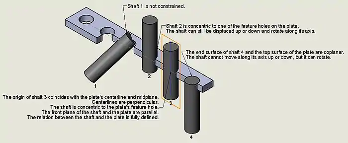
Ideally, a rod will need to be concentric to a hole drilled through the plate where it will be inserted, so the constraint "concentric" guarantees that the diameter of the rod and the diameter of the hole maintain a common centerline, thus "locking" the manner the rod relates to the hole in the plate; this means that the rod could still slide on either direction since the position of its ends has not been limited. Instance 2 illustrates that the rod may still rotate along its centerline while it slides up or down.

See also
References
- Schoonmaker, Stephen J. (2003). The CAD guidebook : a basic manual for understanding and improving computer-aided design. New York: Marcel Dekker. ISBN 0-8247-0871-7. OCLC 50868192.
- The Electronic design studio : architectural knowledge and media in the computer era. Malcolm McCullough, William J. Mitchell, Patrick Purcell. Cambridge, Mass.: MIT Press. 1990. ISBN 0-262-13254-0. OCLC 20692928.
{{cite book}}: CS1 maint: others (link) - J. Mitchell, William (1989). "A New Agenda For Computer-Aided Architectural Design". Massachusetts, US: Harvard University Graduate School of Design.
- Craig, Iain (January 1989). "Constraint Programming Languages: Their Specification And Generation by Wm Leler Addison-Wesley, Reading MA, 1988, 202 pages (incl. index) (£24.95)". Robotica. 7 (1): 85. doi:10.1017/S026357470000521X. ISSN 0263-5747.
- "Understanding Geometric Constraints - AutoCAD® 2012 FOR DUMMIES® [Book]". www.oreilly.com. Retrieved 2022-02-12.
Sources
- Introducing AutoCAD 2010 and AutoCAD LT 2010 (pages 117-122), by George Omura. 2009; 1st. Edition. Wiley Publishing, Inc., Indianapolis, Indiana. ISBN 978-0-470-43867-1 Hard Cover; 384 pages.
- Autodesk® Inventor® 2011 Essentials Plus (pages 312-341), by Daniel T. Banach; Travis Jones; Alan J. Kalameja. 2011; Delmar/Cengage Learning, Autodesk Press. Printed in the United States of America. ISBN 978-1-1111-3527-0; ISBN 1-1111-3527-4. New York.