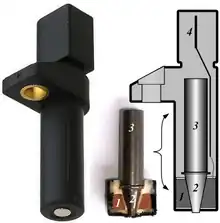
Crankshaft position sensor
A crank sensor (CKP)[1][2][3] is an electronic device used in an internal combustion engine, both petrol and diesel, to monitor the position or rotational speed of the crankshaft. This information is used by engine management systems to control the fuel injection or the ignition system timing and other engine parameters. Before electronic crank sensors were available, the distributor would have to be manually adjusted to a timing mark on petrol engines.

The crank sensor can be used in combination with a similar camshaft position sensor (CMP)[4][5][3] to monitor the relationship between the pistons and valves in the engine, which is particularly important in engines with variable valve timing. This method is also used to "synchronise" a four stroke engine upon starting, allowing the management system to know when to inject the fuel. It is also commonly used as the primary source for the measurement of engine speed in revolutions per minute.
Common mounting locations include the main crank pulley, the flywheel, the camshaft or on the crankshaft itself. This sensor is one of the two most important sensors in modern-day engines, together with the camshaft position sensor. As the fuel injection (diesel engines) or spark ignition (petrol engines) is usually timed from the crank sensor position signal, failing sensor will cause an engine not to start or will cut out while running. Engine speed indicator takes speed indication also from this sensor.
Types of sensors
There are several types of sensors that can be used: the inductive sensor, Hall Effect sensor, magnetoresistive sensor, and optical sensor. Inductive sensors have the simplest construction and are usually purely passive devices. Hall effect and magnetoresistive sensors have the advantage over inductive sensors in that they can detect static (non-changing) magnetic fields. Optical sensors do not have great resistance against fouling but are able to provide the most precise edge detection.
Some engines, such as GM's Premium V family, use crank position sensors which read a reluctor ring integral to the harmonic balancer. This is a much more accurate method of determining the position of the crankshaft and allows the computer to determine, within a few degrees, the exact position of the crankshaft (and thereby all connected components) at any given time.
Function
The functional objective for the crankshaft position sensor is to determine the position and/or rotational speed (RPM) of the crank. Engine Control Units use the information transmitted by the sensor to control parameters such as ignition timing and fuel injection timing. In a diesel, the sensor will control the fuel injection. The sensor output may also be related to other sensor data including the cam position to derive the current combustion cycle, this is very important for the starting of a four-stroke engine.
Sometimes, the sensor may become burnt or worn out - or just die of old age at high mileage. One likely cause of crankshaft position sensor failure is exposure to extreme heat. Others are vibration causing a wire to fracture or corrosion on the pins of harness connectors. Many modern crankshaft sensors are sealed units and therefore will not be damaged by water or other fluids. When it goes wrong, it stops transmitting the signal which contains the vital data for the ignition and other parts in the system.
A bad crank position sensor can worsen the way the engine idles, or the acceleration behaviour. If the engine is revved up with a bad or faulty sensor, it may cause misfiring, motor vibration or backfires. Acceleration might be hesitant, and abnormal shaking during engine idle might occur. In the worst case, the car may not start.
The first sign of crankshaft sensor failure, usually, is the refusal of the engine to start when hot but will start again once the engine has cooled.
One detail of some designs is the "three-wire" inductive crank sensor whereby the third wire is actually just a co-axial shield around the two main sensor wires to prevent them from picking up stray electrical pulses from elsewhere in the vehicle engine bay.
Examples
Another type of crank sensor is used on bicycles to monitor the position of the crankset, usually for the cadence readout of a cyclocomputer. These are usually reed switches mounted on the bicycle frame with a corresponding magnet attached to one of the pedals crankset arms.
Notes
GMR (giant magnetoresistance) technology is also used for Crank, Cam rotor sensing purpose. Mitsubishi is the first who used this technology in automotive application purpose.
See also
References
- McCord, Keith (2011). Automotive Diagnostic Systems: Understanding OBD I and OBD II. CarTech Inc. p. 105. ISBN 978-1-934709-06-1.
- Singh, Mahipal (2020-11-11). I.C. Engine Management System. ICARIANS - Trainer's Hub. p. 11.
- "Basics of Crankshaft & Camshaft Position Sensors". www.aa1car.com. Retrieved 2022-11-17.
- Schnubel, Mark (2019-01-09). Today's Technician: Advanced Engine Performance Classroom Manual and Shop Manual. Cengage Learning. p. 184. ISBN 978-0-357-39065-8.
- Goodnight; VanGelder, Kirk T. (2017-06-30). Automotive Engine Repair. Jones & Bartlett Learning. p. 162. ISBN 978-1-284-10198-0.