Liquid crystal on silicon
Liquid crystal on silicon (LCoS or LCOS) is a miniaturized reflective active-matrix liquid-crystal display or "microdisplay" using a liquid crystal layer on top of a silicon backplane. It is also referred to as a spatial light modulator. LCoS was initially developed for projection televisions but is now used for wavelength selective switching, structured illumination, near-eye displays and optical pulse shaping. By way of comparison, some LCD projectors use transmissive LCD, allowing light to pass through the liquid crystal.
In an LCoS display, a complementary metal–oxide–semiconductor (CMOS) chip controls the voltage on square reflective aluminium electrodes buried just below the chip surface, each controlling one pixel. For example, a chip with XGA resolution will have 1024x768 plates, each with an independently addressable voltage. Typical cells are about 1–3 centimeters square and about 2 mm thick, with pixel pitch as small as 2.79 μm.[1] A common voltage for all the pixels is supplied by a transparent conductive layer made of indium tin oxide on the cover glass.
Displays
History
The history of LCos projectors dates back to the late 1980s when the technology was first developed. At the time, the primary use of LCos projectors was in the military and scientific fields due to their large and bulky size. However, in the late 1990s, companies like JVC and Hughes Electronics began developing smaller and more affordable LCos projectors for commercial use.
The early LCos projectors had their challenges. They suffered from a phenomenon called "image sticking," where the image would remain on the screen after it was supposed to be gone. This was due to the mirrors sticking in their positions, which resulted in ghosting on the screen. However, manufacturers continued to refine the technology, and today's LCos projectors have largely overcome this issue.
One of the biggest milestones in the history of LCos projectors came in 2004 when Sony introduced its SXRD (Silicon X-tal Reflective Display) technology. SXRD was an evolution of LCos technology that used even smaller pixels and a higher resolution, resulting in an even more accurate image. The SXRD technology was used in Sony's high-end home theater projectors, and it quickly gained a reputation for its exceptional picture quality.
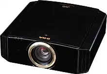
Another significant development in the history of LCos projectors came in 2006 when JVC introduced its D-ILA (Direct-Drive Image Light Amplifier) technology. D-ILA was an improvement over traditional LCos projectors in that it eliminated the need for a polarizing filter, resulting in a brighter and more vibrant image. The D-ILA technology has since become a popular choice for home theater enthusiasts.
In recent years, LCos projectors have continued to evolve, with manufacturers introducing features like 4K resolution and HDR (High Dynamic Range) support. LCos projectors are now available at a range of price points, from affordable models for home theater use to high-end professional models used in commercial installations.
Overall, the history of LCos projectors is one of innovation and improvement. From their early days as bulky military and scientific equipment to today's sleek and affordable consumer models, LCos projectors have come a long way. Their high image quality, accurate color reproduction, and other advantages have made them a popular choice for home theater enthusiasts and professionals alike.
Display system architectures
LCos (Liquid Crystal on Silicon) display technology is a type of microdisplay that has gained popularity due to its high image quality and ability to display high-resolution images. LCos display systems typically consist of three main components: the LCos panel, the light source, and the optical system.
The LCos panel is the heart of the display system. It consists of an array of pixels that are arranged in a grid pattern. Each pixel is made up of a liquid crystal layer, a reflective layer, and a silicon substrate. The liquid crystal layer controls the polarization of light that passes through it, while the reflective layer reflects the light back towards the optical system. The silicon substrate is used to control the individual pixels and provides the necessary electronics to drive the LCos panel.
The light source is used to provide the necessary illumination for the LCos panel. The most common light source used in LCos display systems is a high-intensity lamp. This lamp emits a broad spectrum of light that is filtered through a color wheel or other optical components to provide the necessary color gamut for the display system.
The optical system is responsible for directing the light from the light source onto the LCos panel and projecting the resulting image onto a screen or other surface. The optical system consists of a number of lenses, mirrors, and other optical components that are carefully designed and calibrated to provide the necessary magnification, focus, and color correction for the display system.
There are two main types of LCos display systems: transmissive and reflective. Transmissive LCos displays use a backlight behind the LCos panel to provide illumination, while reflective LCos displays use the ambient light in the environment to illuminate the LCos panel. Reflective LCos displays are more power-efficient and offer better contrast ratios than transmissive displays, but are typically more expensive to manufacture.
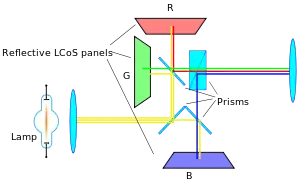
Three-panel designs
The white light is separated into three components (red, green and blue) and then combined back after modulation by the 3 LCoS devices. The light is additionally polarized by beam splitters.
One-panel designs
Both Toshiba's and Intel's single-panel LCOS display program were discontinued in 2004 before any units reached final-stage prototype.[2] There were single-panel LCoS displays in production: One by Philips and one by Microdisplay Corporation. Forth Dimension Displays continues to offer a Ferroelectric LCoS display technology (known as Time Domain Imaging) available in QXGA, SXGA and WXGA resolutions which today is used for high resolution near-eye applications such as Training & Simulation, structured light pattern projection for AOI. Citizen Finedevice (CFD) also continues to manufacturer single panel RGB displays using FLCoS technology (Ferroelectric Liquid Crystals). They manufacture displays in multiple resolutions and sizes that are currently used in pico-projectors, electronic viewfinders for high end digital cameras, and head-mounted displays.[3]
Pico projectors, near-eye and head-mounted displays
Whilst initially developed for large-screen projectors, LCoS displays have found a consumer niche in the area of pico-projectors, where their small size and low power consumption are well-matched to the constraints of such devices.
LCoS devices are also used in near-eye applications such as electronic viewfinders for digital cameras, film cameras, and head-mounted displays (HMDs). These devices are made using ferroelectric liquid crystals (so the technology is named FLCoS) which are inherently faster than other types of liquid crystals to produce high quality images.[4] Google's initial foray into wearable computing, Google glass,[5] also uses a near-eye LCoS display.
At CES 2018, Hong Kong Applied Science and Technology Research Institute Company Limited (ASTRI) and OmniVision showcased a reference design for a wireless augmented reality headset that could achieve 60 degree field of view (FoV). It combined a single-chip 1080p LCOS display and image sensor from OmniVision with ASTRI's optics and electronics. The headset is said to be smaller and lighter than others because of its single-chip design with integrated driver and memory buffer.[6]
Wavelength-selective switches
LCoS is particularly attractive as a switching mechanism in a wavelength-selective switch (WSS). LCoS-based WSS were initially developed by Australian company Engana,[7] now part of Finisar.[8] The LCoS can be employed to control the phase of light at each pixel to produce beam-steering[9] where the large number of pixels allow a near continuous addressing capability. Typically, a large number of phase steps are used to create a highly efficient, low-insertion loss switch shown. This simple optical design incorporates polarisation diversity, control of mode size and a 4-f wavelength optical imaging in the dispersive axis of the LCoS providing integrated switching and optical power control.[10]
In operation, the light passes from a fibre array through the polarisation imaging optics which separates physically and aligns orthogonal polarisation states to be in the high efficiency s-polarisation state of the diffraction grating. The input light from a chosen fibre of the array is reflected from the imaging mirror and then angularly dispersed by the grating which is at near Littrow incidence, reflecting the light back to the imaging optics which directs each channel to a different portion of the LCoS. The path for each wavelength is then retraced upon reflection from the LCoS, with the beam-steering image applied on the LCOS directing the light to a particular port of the fibre array. As the wavelength channels are separated on the LCoS the switching of each wavelength is independent of all others and can be switched without interfering with the light on other channels. There are many different algorithms that can be implemented to achieve a given coupling between ports including less efficient "images" for attenuation or power splitting.
WSS based on MEMS[11] and/or liquid crystal[12] technologies allocate a single switching element (pixel) to each channel which means the bandwidth and centre frequency of each channel are fixed at the time of manufacture and cannot be changed in service. In addition, many designs of first-generation WSS (particularly those based on MEMs technology) show pronounced dips in the transmission spectrum between each channel due to the limited spectral ‘fill factor’ inherent in these designs. This prevents the simple concatenation of adjacent channels to create a single broader channel.
LCoS-based WSS, however, permit dynamic control of channel centre frequency and bandwidth through on-the-fly modification of the pixel arrays via embedded software. The degree of control of channel parameters can be very fine-grained, with independent control of the centre frequency and either upper- or lower-band-edge of a channel with better than 1 GHz resolution possible. This is advantageous from a manufacturability perspective, with different channel plans being able to be created from a single platform and even different operating bands (such as C and L) being able to use an identical switch matrix. Additionally, it is possible to take advantage of this ability to reconfigure channels while the device is operating. Products have been introduced allowing switching between 50 GHz channels and 100 GHz channels, or a mix of channels, without introducing any errors or "hits" to the existing traffic. More recently, this has been extended to support the whole concept of Flexible or Elastic networks under ITU G.654.2 through products such as Finisar's Flexgrid™ WSS.
Other LCoS applications
Optical pulse shaping
The ability of an LCoS-based WSS to independently control both the amplitude and phase of the transmitted signal leads to the more general ability to manipulate the amplitude and/or phase of an optical pulse through a process known as Fourier-domain pulse shaping.[13] This process requires full characterisation of the input pulse in both the time and spectral domains.
As an example, an LCoS-based Programmable Optical Processor (POP) has been used to broaden a mode-locked laser output into a 20 nm supercontinuum source whilst a second such device was used to compress the output to 400 fs, transform-limited pulses.[14] Passive mode-locking of fiber lasers has been demonstrated at high repetition rates, but inclusion of an LCoS-based POP allowed the phase content of the spectrum to be changed to flip the pulse train of a passively mode-locked laser from bright to dark pulses.[15] A similar approach uses spectral shaping of optical frequency combs to create multiple pulse trains. For example, a 10 GHz optical frequency comb was shaped by the POP to generate dark parabolic pulses and Gaussian pulses, at 1540 nm and 1560 nm, respectively.[16]
Light structuring
Structured light using a fast ferroelectric LCoS is used in 3D-superresolution microscopy techniques and in fringe projection for 3D-automated optical inspection.
Modal switching in space division multiplexed optical communications systems
One of the interesting applications of LCoS is the ability to transform between modes of few-moded optical fibers[17] which have been proposed as the basis of higher capacity transmission systems in the future. Similarly LCoS has been used to steer light into selected cores of multicore fiber transmission systems, again as a type of Space Division Multiplexing.
Tunable lasers
LCoS has been used as a filtering technique, and hence a tuning mechanism, for both semiconductor diode and fiber lasers.[18]
See also
- Digital Light Processing – Set of chipsets
References
- Compound Photonics. "Products Compound Photonics". Archived from the original on October 18, 2014. Retrieved October 13, 2014.
- Hachman, Mark. "Update: Intel Cancels LCOS Chip Plans". 415.992.5910. Extreme Tech. Retrieved June 17, 2011.
- Homepage for MDCA a subsidiary of Citizen Finedevice
- Collings, N. (2011). "The Applications and Technology of Phase-Only Liquid Crystal on Silicon Devices". IEEE Journal of Display Technology. 7 (3): 112–119. Bibcode:2011JDisT...7..112C. doi:10.1109/JDT.2010.2049337. S2CID 34118772.
- Google glass. google.com
- "This AR Headset Surpasses the Field of View of HoloLens, but You Still Won't Wear It in Public". Next Reality. January 11, 2018. Retrieved June 23, 2020.
- Baxter, G. et al. (2006) "Highly Programmable Wavelength Selective Switch Based on Liquid Crystal on ," in Optical Fiber Communication Conference, 2006 and the 2006 National Fiber Optic Engineers Conference.
- ROADMs & Wavelength Management. finisar.com
- Johnson, K. M. (1993). "Smart spatial light modulators using liquid crystals on silicon". IEEE J. Quantum Electron. 29 (2): 699–714. Bibcode:1993IJQE...29..699J. doi:10.1109/3.199323.
- Kaminov, Li and Wilner (ed.). "Ch. 16". Optical Fiber Telecommunications VIA. Academic Press. ISBN 978-0-12-396958-3.
- Marom, D. M. et al. (2002) "Wavelength-selective 1×4 switch for 128 WDM channels at 50 GHz spacing," in Proc. Optical Fiber Communications), Anaheim, CA, Postdeadline Paper FB7, pp. FB7-1–FB7-3
- Kondis, J. et al. (2001) "Liquid crystals in bulk optics-based DWDM optical switches and spectral equalizers," pp. 292–293 in Proc. LEOS 2001, Piscataway, NJ.
- Weiner, A.M. (2000). "Femtosecond pulse shaping using spatial light modulators" (PDF). Rev. Sci. Instrum. 71 (5): 1929–1960. Bibcode:2000RScI...71.1929W. doi:10.1063/1.1150614.
- A. M. Clarke, D. G. Williams, M. A. F. Roelens, M. R. E. Lamont, and B. J. Eggleton, "Parabolic pulse shaping for enhanced continuum generation using an LCoS-based wavelength selective switch," in 14th OptoElectronics and Communications Conference (OECC) 2009.
- Schroeder, Jochen B. (2010). "Dark and Bright Pulse Passive Mode-locked Laser with In-cavity Pulse-shaper". Optics Express. 18 (22): 22715–22721. Bibcode:2010OExpr..1822715S. doi:10.1364/OE.18.022715. PMID 21164610.
- Ng, T. T. et al. (2009) "Complete Temporal Optical Fourier Transformations Using Dark Parabolic Pulses," in 35th European Conference on Optical Communication.
- Salsi, Massimiliano; Koebele, Clemens; Sperti, Donato; Tran, Patrice; Mardoyan, Haik; Brindel, Patrick; Bigo, Sébastien; Boutin, Aurélien; Verluise, Frédéric; Sillard, Pierre; Astruc, Marianne; Provost, Lionel; Charlet, Gabriel (2012). "Mode-Division Multiplexing of 2×100 Gb/s Channels Using an LCOS-Based Spatial Modulator". Journal of Lightwave Technology. 30 (4): 618. Bibcode:2012JLwT...30..618S. doi:10.1109/JLT.2011.2178394. S2CID 38004325.
- Xiao, Feng (2009). "Opto-VLSI-based Tunable Single-mode Fiber Laser". Optics Express. 17 (21): 18676–18680. Bibcode:2009OExpr..1718676X. doi:10.1364/OE.17.018676. PMID 20372600.
External links
- Biever, Celeste. 'Intel inside' comes to flat panel TVs (January 9, 2004 – No longer planned for development) New Scientist
- Everything You Need to Know About TV Technologies from Hardware Secrets