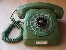
Rotary dial
A rotary dial is a component of a telephone or a telephone switchboard that implements a signaling technology in telecommunications known as pulse dialing. It is used when initiating a telephone call to transmit the destination telephone number to a telephone exchange.
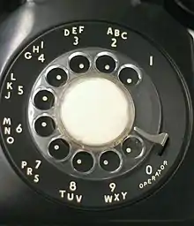
On the rotary dial, the digits are arranged in a circular layout, with one finger hole in the finger wheel for each digit. For dialing a digit, the wheel is rotated against spring tension with one finger positioned in the corresponding hole, pulling the wheel with the finger to a stop position given by a mechanical barrier, the finger stop. When released at the finger stop, the wheel returns to its home position driven by the spring at a speed regulated by a governor device. During this return rotation, an electrical switch interrupts the direct current (DC) of the telephone line (local loop) the specific number of times associated with each digit and thereby generates electrical pulses which the telephone exchange decodes into each dialed digit. Thus, each of the ten digits is encoded in sequences to correspond to the number of pulses; thus, the method is sometimes called decadic dialing.
The first patent for a rotary dial was granted to Almon Brown Strowger on November 29, 1892, but the commonly known form with holes in the finger wheel was not introduced until about 1904. While used in telephone systems of the independent telephone companies, rotary dial service in the Bell System in the United States was not common until the early 1920s.[1]
From the 1960s onward, the rotary dial was gradually supplanted by DTMF (dual-tone multi-frequency) push-button dialing, first introduced to the public at the 1962 World's Fair under the trade name "Touch-Tone". Touch-tone technology primarily used a keypad in the form of a rectangular array of push-buttons. Although no longer in common use, the rotary dial's legacy remains in the verb "to dial (a telephone number)".
History

From as early as 1836 onward, various suggestions and inventions of dials for sending telegraph signals were reported. After the first commercial telephone exchange was installed in 1878, the need for an automated, user-controlled method of directing a telephone call became apparent. Addressing the technical shortcomings, Almon Brown Strowger invented a telephone dial in 1891.[2] Before 1891, numerous competing inventions, and 26 patents for dials, push-buttons, and similar mechanisms, specified methods of signalling a destination telephone station that a subscriber wanted to call. Most inventions involved costly, intricate mechanisms and required the user to perform complex manipulations.
The first commercial installation of a telephone dial accompanied the first commercial installation of a 99-line automatic telephone exchange in La Porte, Indiana, in 1892, which was based on the 1891 Strowger designs. The original dials required complex operational sequences. A workable, albeit error-prone, system was invented by the Automatic Electric Company using three push-buttons on the telephone. These buttons represented the hundreds, tens, and single units of a telephone number. When calling the subscriber number 163, for example, the user had to push the hundreds button once, followed by six presses of the tens button, and three presses of the units button.[3] In 1896, this system was supplanted by an automatic contact-making machine, or calling device. Further development continued during the 1890s and the early 1900s in conjunction with improvements in switching technology.
Almon Brown Strowger was the first to file a patent for a rotary dial on December 21, 1891, which was awarded on November 29, 1892, as U.S. Patent 486,909.[4][5] The early rotary dials used lugs on a finger plate instead of holes, and did not produce a linear sequence of pulses, but interrupted two independent circuits for control of relays in the exchange switch. The pulse train was generated without the control of spring action or a governor on the forward movement of the wheel, which proved to be difficult to operate correctly.
Despite their lack of modern features, rotary dials occasionally find special uses, particularly in industrial equipment. For instance, the anti-drug Fairlawn Coalition of the Anacostia section of Washington, D.C., persuaded the phone company to reinstall rotary-dial pay phones in the 1980s to discourage loitering by drug purchasers, since they lacked a telephone keypad to leave messages on dealers' pagers.[6] They are also retained for authenticity in historic properties such as the U.S. Route 66 Blue Swallow Motel, which date back to the era of named exchanges and pulse dialing.[7]
Function
For dialing a digit of the telephone number, the user inserts a finger into the corresponding finger hole and rotates the dial clockwise until the finger reaches the finger stop. The user then releases the finger wheel by pulling the finger from the hole. A spring around the dial shaft rotates it back to the rest position. During the period of return, the dial operates electrical contacts that break the electrical continuity of the local loop, and interrupt the current flow a certain number of times for each digit marked on the front of the dial.
The number of pulses sent for each digit is defined by the type of dial system in use. The encoding has traditionally varied by country, or by the manufacturer of the telephone system. For example, Sweden used one pulse to signal the number zero, and ten pulses to signal the number nine. In Finland, where many telephones were of Swedish manufacture, one pulse signaled digit 1, and ten pulses 0. New Zealand used ten pulses minus the number desired; so dialing the digit 7 produces three pulses. In Norway, the North American system with the digit 1 corresponding to one pulse was used, except for the capital city, Oslo, which used the same "inverse" system as in New Zealand. The sequencing of the digits on the dial varies accordingly.
Rotary dials have no redial feature; the entire telephone number must be dialed for every attempted call. The time it took for dialing depended on the digit, i.e. how far the dial had to travel to return to the rest position.
Construction
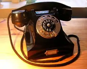
A rotary dial typically features a circular construction. The shaft that actuates the mechanical switching mechanism is driven by the finger wheel, a disk that has ten finger holes aligned close to the circumference. The finger wheel may be transparent or opaque permitting the viewing of the face plate (number plate), either in whole, or only showing the number assignment for each finger hole. The faceplate is printed with digits, and often letters, corresponding to each finger hole. Digit 1 is typically set in the upper right quadrant of the dial front, then the numbers progress counterclockwise. A curved device, the finger stop is positioned in the lower right quadrant. Some dialing mechanism allowed the use of physical locking mechanisms to prevent unauthorized use. The lock could be integral to the telephone itself or a separate device inserted through the finger hole nearest the finger stop to prevent the dial from rotating.
The rotational return speed of the dial to its rest position is controlled by the governor, a mechanical regulating device, that assures a constant electrical pulsing rate of the dial.
Principal dial mechanisms in the United States
In the United States, two principal dial mechanisms arose in the engineering laboratories of the largest manufacturers, that of the Western Electric Company for the Bell System, and that of the Automatic Electric Company.
The Western Electric dial had spur gears to power the governor, so the axis of the governor was parallel to the dial shaft. The Automatic Electric governor shaft was parallel to the plane of the dial at a right angle to the dial shaft. The governor shaft had worm gearing in which, very atypically, the gear drove the worm. The worm, highly polished, had extreme pitch, with teeth at about 45° to its axis. This was the same as the gearing for the speed-limiting fan in traditional music boxes. The Western Electric governor was a cup surrounding spring-loaded pivoted weights with friction pads. The Automatic Electric governor had weights on the middle of curved springs made from strip stock. When it sped up after the dial was released, the weights moved outward, pulling the ends of their springs together. Springs were fixed to a collar on the shaft at one end and to the hub of a sliding brake disc at the other end. At speed, the brake disc contacted a friction pad. This governor was similar to that in spring-driven windup phonograph turntables of the early 20th century.
Both types had wrap-spring clutches for driving their governors. When winding the dial-return spring, these clutches disconnected to let the dial turn quickly. When the dial was released, the clutch spring wrapped tightly to drive the governor.
While winding the dial, a spring-centered pawl in the Western Electric dial wiggled off-center when driven by the cam on the dial shaft. Teeth on that cam were spaced apart by the same angle as dial hole spacing. During winding, the pawl moved off-center away from the normally-closed pulsing contacts. When the dial was released, the cam teeth moved the pawl the other way to open and release the dial contacts. In the Automatic Electric dial, the pulsing cam and governor were driven by a wrap-spring clutch as the dial returned. When winding, that clutch disconnected both cam and governor.
Recoil spring
Early dials worked by direct or forward rotating action. The pulses were generated as the dial turned toward the finger stop position. When the user's hand motion was erratic, it could produce the wrong digit. In the late 19th century, the dial was refined to operate automatically by a recoil spring. The user selected the digit to be dialed, rotated the dial to the finger stop, then released it. The spring caused the dial to rotate back to its home position during which time constant speed was maintained with a centrifugal governor.
Dials at user stations typically produced pulses at the rate of ten pulses per second (PPS), while dials on operator consoles on crossbar or electronic exchanges often pulsed at 18 PPS.
The rotary dial governor is subject to wear and aging, and may require periodic cleaning, lubrication and adjustment by a technician. In the video, the green LED shows the dial impulse pulses and the red LED shows the dial's off-normal contact function.
Off-normal contacts typically serve two additional functions. They may implement a shunt across the transmitter circuit and induction coil to maximize the pulsing signal of the dial by eliminating all internal impedances of the telephone set. Another function is to short-circuit or interrupt the telephone receiver during dialing, to prevent audible clicking noise from being heard by the telephone user.
Dials located in handsets
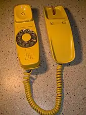
Some telephones include a small dial built into the handset, with a movable finger stop. The user rotates the dial clockwise until the finger stop ceases moving, then releases both. In this design the holes extend around the full circumference of the dial, allowing a reduced diameter. This was introduced by Western Electric on the compact Trimline telephone, the first to locate the dial in the handset. In Spain, such phones were manufactured for CTNE (Compañía Telefónica Nacional de España) by Málaga-based factory "CITESA", being named as "Góndola" phones by its particular shape. Spanish Góndola sets were fitted from the beginning with a red LED series connected with the line, allowing the dial ("disco" in Spanish) to be backlit while dialling. For that, the LED was bridged by an anti-parallel Zener diode, to allow the DC to pass even if the line polarity were reversed. In case of line polarity reversal, the LED would not light, but the phone would work anyway. The LED and Zener diode were contained in the same package for ease of assembly in manufacturing.
Britain

In the United Kingdom the letter "O" was combined with the digit "0" rather than "6". In large cities the seven-digit numbers comprised three letters for the exchange name, followed by four numbers.
Australia

Before 1960 Australian rotary dial telephones had each number's corresponding letter printed on a paper disc in the centre of the plate, with space where the subscriber could add the phone number. The paper was protected by a clear plastic disc, held in place by a form of retaining ring which also served to locate the disc radially. The Australian letter-to-number mapping was A=1, B=2, F=3, J=4, L=5, M=6, U=7, W=8, X=9, Y=0, so the phone number BX 3701 was in fact 29 3701. When Australia around 1960 changed to all-numeric telephone dials, a mnemonic to help people associate letters with numbers was the sentence, "All Big Fish Jump Like Mad Under Water eXcept Yabbies."
Eastern bloc
Alphabetic designation of exchanges with Cyrillic letters (А, Б, В, Г, Д, Е, Ж, И, К, Л for each of the digits from 1 through 0 respectively) was also used for a short period in the Soviet Union in the 1950s and 1960s, but by the next decade this practice was largely discontinued.[8][9]
Letter codes were not used in all East European countries.

Emergency calling
A relic of these differences is found in emergency telephone numbers used in various countries; the United Kingdom selected 999 due to the ease of converting call office dials to make free calls. "0" for the Operator was already free, and the cam that removed the shunt on the line when the dial was rotated to the "0" position could be altered to include the adjacent digit "9" (and "8" if required) so that calls to "0" and "999" could be made without inserting coins. In New Zealand, 111 was selected because New Zealand reverse-numbered dials make each digit "1" send 9 pulses to the central office/telephone exchange (like "9" in Britain), allowing British exchange equipment to be used off the shelf.
Alphanumeric dialing
In addition to the ten digits, the faceplate is often printed with letters corresponding to each position.
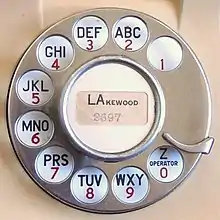
In North America, traditional dials have letter codes displayed with the numbers under the finger holes in the following pattern: 1, 2 ABC, 3 DEF, 4 GHI, 5 JKL, 6 MNO, 7 PRS, 8 TUV, 9 WXY, and 0 (sometimes Z) Operator. Letters were associated with the dial numbers to represent telephone exchange names in communities that required multiple central offices. For example, "RE7-3456" represented "REgent 7-3456".
In 1917, W. G. Blauvelt of AT&T developed the combination pattern of letters assigned to each digit, which became the standard in North America. Large cities like New York City would ultimately require a seven-digit telephone number. Some tests in the early 1900s indicated that the short-term memory span of many people was insufficient for seven digits, causing dialing errors (the documentation for these tests is lost). As large cities had both manual and automatic exchanges for many years, the numbers for manual or automatic exchanges used the same format, which could be either spoken or dialed.[10]
In the late 1940s, telephones were redesigned with the numbers and letters displayed on a ring outside the finger wheel to provide better visibility.[11]
Push-button pulse dialing
Even after the transition to DTMF dialing with push-button keypads in most areas, pulse-dialing telephones continued to be produced for some time, even with keypads for dialing, for use with certain private exchange systems.[12] Some of these can be distinguished visually by the lack of keys with the symbols # and *. Some telephones may have an option to select pulse dialing or DTMF dialing.
See also
- AIOD leads (automatic identified outward dialing)
- Crossbar switch
- Dial tone
- Direct distance dialing (DDD)
- History of the telephone
- Single-frequency signaling
- Stepping switch
- Title 47 CFR Part 68
References
- Roberts, William Lee. "A look at the evolution of the Dial Telephone". Retrieved 15 January 2016.
- Fiber Optics Weekly Update. Information Gatekeepers Inc.
- Smith, A. B.; Campbell, W. L., Automatic Telephony, New York, McGraw-Hill, 1921, p. 38.
- Greenman, Catherine (October 7, 1999). "When Dials Were Round and Clicks Were Plentiful". The New York Times. Archived from the original on 2007-06-16 – via oldphones.com.
- "Automatic Telephone or Other Electrical Exchange". United States Patent and Trademark Office.
- Benson, Bruce L. (1998). "Private Justice in America". To Serve and Protect: Privatization and Community in Criminal Justice. NYU Press. pp. 123–124. ISBN 0-8147-1327-0.
- John Flinn (October 5, 2012). "Route 66 still has some kicks". San Francisco Chronicle. Retrieved 2012-10-08.
- History of Moscow City Telephone Network Archived 2014-07-09 at archive.today (in Russian)
- A short history of telephone numbers, includes a copy of the 1968 flyer about abolishing letters in Moscow telephone numbers from the museum of Moscow City Telephone Network
- A History of Engineering and Science in the Bell System: The Early Years (1875-1925) p578 by M. D. Fagen (editor) & Bell Labs technical staff (1975, Bell Telephone Laboratories)
- Vanderbilt, Tom (2012-05-15). "Hello?". Slate. ISSN 1091-2339. Retrieved 2017-02-04.
- "TELEPHONE No. 728". www.britishtelephones.com. Retrieved May 6, 2017.
External links
- "The Invention and Development of the Dial Telphone [sic]: The Contribution of Three Lindsborg Inventors" by Emory Lindquist; Spring 1957 issue of The Kansas Historical Quarterly
- "How Your Dial Phone Works", Popular Science, August 1946—detailed article on subject with illustrations
- AT&T Archives Director's Cut - Now You Can Dial (YouTube), from the AT&T archives
