Slurry wall
A slurry wall is a civil engineering technique used to build reinforced concrete walls in areas of soft earth close to open water, or with a high groundwater table.[1] This technique is typically used to build diaphragm (water-blocking) walls surrounding tunnels and open cuts, and to lay foundations. Slurry walls are used at Superfund sites to contain the waste or contamination and reduce potential future migration of waste constituents, often with other waste treatment methods. Slurry walls are a "well-established" technology but the decision to use slurry walls for a certain project requires geophysical and other engineering studies to develop a plan appropriate for the needs of that specific location. Slurry walls may need to be used in conjunction with other methods to meet project objectives.[2]

Construction

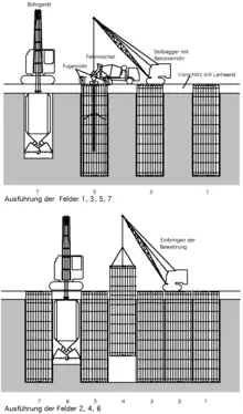
While a trench is being excavated to create a form for a wall, it is simultaneously filled with slurry (usually a mixture of bentonite and water). The dense but liquid slurry prevents the trench from collapsing by providing outward pressure, which balances the inward hydraulic forces and also retards water flow into the trench. The density of the slurry mix must be carefully monitored and adjusted to produce the correct outward pressure to prevent the trench walls from collapsing.
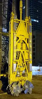
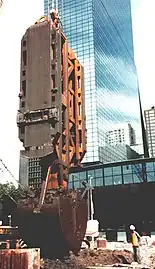
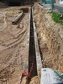
Slurry walls are typically constructed by starting with a set of concrete guide walls, typically 1 metre (3 ft 3 in) deep and 0.5 metres (1 ft 8 in) thick. The guide walls are constructed near the ground surface to outline the desired slurry trench, and to guide the excavation machinery. Excavation is done using a special clamshell-shaped digger or a hydromill trench cutter, suspended from a crane. The excavator digs down to design depth (or bedrock) for the first wall segment. The excavator is then lifted and moved along the trench guide walls to continue the trench with successive cuts as needed. The trench is at all times kept filled with slurry to prevent its collapse, but the fluid filling allows the excavation machinery and excavation spoil to be moved without hindrance.
Once a particular depth of trench is reached, a reinforcing cage is lowered into the slurry-filled pit and the pit is filled with concrete from the bottom up using tremie pipes. The heavier concrete displaces the bentonite slurry, which is pumped out, filtered, and stored in tanks for use in the next wall segment, or it is recycled.
Slurry walls are successively extended to enclose an area, blocking water and softened earth from flowing into it. Once the concrete has hardened, excavation within the now concrete-wall-enclosed area can proceed. To prevent the concrete wall from collapsing into the newly excavated area, temporary supports such as tiebacks or internal crossbeams are installed. When completed, the structure built within the walled-off area usually supports the wall, so that tiebacks or other temporary bracing may be optionally removed.
History
The slurry wall technique was first introduced in the 1950s during the excavations of the Red Line of the Milan Metro in Italy by the company ICOS (Impresa Costruzioni Opere Specializzate). This new technology became an important component of the top-down tunnelling method also known as Metodo Milano ("Milan method").[3]
Slurry wall construction was used in 1967–1968 to construct the "bathtub" that surrounded the foundations of most of the World Trade Center site in New York City.[4] In the 1980s, the Red Line Northwest Extension project in Boston was one of the first projects in the US to use the modern form of the technology, with hydromill trench cutters and the "Milan method". Slurry walls were also used extensively in Boston's 1990s Big Dig tunnel project.
Design
The design of a slurry wall (diaphragm wall) includes the design of wall thickness and reinforcements. Thickness of a slurry wall in preliminary design is generally set to about 4-8% of the excavation depth. Slurry wall design is undertaken based on bending moment and shear envelope obtained from the stress analysis. In the design of such underground walls, width of the unit is considered as one meter, and the wall is analyzed under plane strain condition. Since the length-to-width ratio of excavations is generally large, plane strain conditions can be assumed.[5]
In a single-phase diaphragm wall, also known as a "cut-off wall", a binder (usually cement) is added to the supporting fluid so that the supporting fluid hardens without exchange.[6] One application for this type of construction is a landfill seal that is to be retrofitted later.
Gallery

 Clamshell-type slurry wall excavator
 A set of slurry wall guide walls before excavation
References
- Gutberle (1994). "Slurry Walls". Virginia Tech. Archived from the original on 2007-08-24. Retrieved 2012-01-05.
- "Engineering Bulletin: Slurry Walls". United States EPA.
- "Primo by Ex Libris -". Retrieved 2015-08-25.
- David W. Dunlap (September 11, 2013). "Looking to a Wall That Limited the World Trade Center's Devastation". New York Times. Retrieved September 11, 2013.
A portion of the slurry wall was deliberately left exposed in the Foundation Hall of the National September 11 Memorial Museum, set to open next year.
- Bahrami, M.; Khodakarami, M.I.; Haddad, A. (April 2019). "Seismic behavior and design of strutted diaphragm walls in sand". Computers and Geotechnics. 108: 75–87. doi:10.1016/j.compgeo.2018.12.019.
- "(Ab)Dicht(ungs)(schlitz)wand f", Wörterbuch GeoTechnik/Dictionary Geotechnical Engineering, Berlin, Heidelberg: Springer Berlin Heidelberg, pp. 7–7, 2013, retrieved 2022-03-28