Closed-loop controller
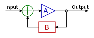
A closed-loop controller or feedback controller is a control loop which incorporates feedback, in contrast to an open-loop controller or non-feedback controller. A closed-loop controller uses feedback to control states or outputs of a dynamical system. Its name comes from the information path in the system: process inputs (e.g., voltage applied to an electric motor) have an effect on the process outputs (e.g., speed or torque of the motor), which is measured with sensors and processed by the controller; the result (the control signal) is "fed back" as input to the process, closing the loop.

In the case of linear feedback systems, a control loop including sensors, control algorithms, and actuators is arranged in an attempt to regulate a variable at a setpoint (SP). An everyday example is the cruise control on a road vehicle; where external influences such as hills would cause speed changes, and the driver has the ability to alter the desired set speed. The PID algorithm in the controller restores the actual speed to the desired speed in an optimum way, with minimal delay or overshoot, by controlling the power output of the vehicle's engine. Control systems that include some sensing of the results they are trying to achieve are making use of feedback and can adapt to varying circumstances to some extent. Open-loop control systems do not make use of feedback, and run only in pre-arranged ways.
Closed-loop controllers have the following advantages over open-loop controllers:
- disturbance rejection (such as hills in the cruise control example above)
- guaranteed performance even with model uncertainties, when the model structure does not match perfectly the real process and the model parameters are not exact
- unstable processes can be stabilized
- reduced sensitivity to parameter variations
- improved reference tracking performance
In some systems, closed-loop and open-loop control are used simultaneously. In such systems, the open-loop control is termed feedforward and serves to further improve reference tracking performance.
A common closed-loop controller architecture is the PID controller.

Open-loop and closed-loop

Fundamentally, there are two types of control loop: open-loop control (feedforward), and closed-loop control (feedback).
In open-loop control, the control action from the controller is independent of the "process output" (or "controlled process variable"). A good example of this is a central heating boiler controlled only by a timer, so that heat is applied for a constant time, regardless of the temperature of the building. The control action is the switching on/off of the boiler, but the controlled variable should be the building temperature, but is not because this is open-loop control of the boiler, which does not give closed-loop control of the temperature.
In closed loop control, the control action from the controller is dependent on the process output. In the case of the boiler analogy this would include a thermostat to monitor the building temperature, and thereby feed back a signal to ensure the controller maintains the building at the temperature set on the thermostat. A closed loop controller therefore has a feedback loop which ensures the controller exerts a control action to give a process output the same as the "reference input" or "set point". For this reason, closed loop controllers are also called feedback controllers.[1]
The definition of a closed loop control system according to the British Standard Institution is "a control system possessing monitoring feedback, the deviation signal formed as a result of this feedback being used to control the action of a final control element in such a way as to tend to reduce the deviation to zero."[2]
Likewise; "A Feedback Control System is a system which tends to maintain a prescribed relationship of one system variable to another by comparing functions of these variables and using the difference as a means of control."[3]Closed-loop transfer function
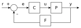
The output of the system y(t) is fed back through a sensor measurement F to a comparison with the reference value r(t). The controller C then takes the error e (difference) between the reference and the output to change the inputs u to the system under control P. This is shown in the figure. This kind of controller is a closed-loop controller or feedback controller.
This is called a single-input-single-output (SISO) control system; MIMO (i.e., Multi-Input-Multi-Output) systems, with more than one input/output, are common. In such cases variables are represented through vectors instead of simple scalar values. For some distributed parameter systems the vectors may be infinite-dimensional (typically functions).

If we assume the controller C, the plant P, and the sensor F are linear and time-invariant (i.e., elements of their transfer function C(s), P(s), and F(s) do not depend on time), the systems above can be analysed using the Laplace transform on the variables. This gives the following relations:
Solving for Y(s) in terms of R(s) gives
The expression is referred to as the closed-loop transfer function of the system. The numerator is the forward (open-loop) gain from r to y, and the denominator is one plus the gain in going around the feedback loop, the so-called loop gain. If , i.e., it has a large norm with each value of s, and if , then Y(s) is approximately equal to R(s) and the output closely tracks the reference input.
PID feedback control

A proportional–integral–derivative controller (PID controller) is a control loop feedback mechanism control technique widely used in control systems.
A PID controller continuously calculates an error value e(t) as the difference between a desired setpoint and a measured process variable and applies a correction based on proportional, integral, and derivative terms. PID is an initialism for Proportional-Integral-Derivative, referring to the three terms operating on the error signal to produce a control signal.
The theoretical understanding and application dates from the 1920s, and they are implemented in nearly all analogue control systems; originally in mechanical controllers, and then using discrete electronics and later in industrial process computers. The PID controller is probably the most-used feedback control design.
If u(t) is the control signal sent to the system, y(t) is the measured output and r(t) is the desired output, and e(t) = r(t) − y(t) is the tracking error, a PID controller has the general form
The desired closed loop dynamics is obtained by adjusting the three parameters KP, KI and KD, often iteratively by "tuning" and without specific knowledge of a plant model. Stability can often be ensured using only the proportional term. The integral term permits the rejection of a step disturbance (often a striking specification in process control). The derivative term is used to provide damping or shaping of the response. PID controllers are the most well-established class of control systems: however, they cannot be used in several more complicated cases, especially if MIMO systems are considered.
Applying Laplace transformation results in the transformed PID controller equation
with the PID controller transfer function
As an example of tuning a PID controller in the closed-loop system H(s), consider a 1st order plant given by
where A and TP are some constants. The plant output is fed back through
where TF is also a constant. Now if we set , KD = KTD, and , we can express the PID controller transfer function in series form as
Plugging P(s), F(s), and C(s) into the closed-loop transfer function H(s), we find that by setting
H(s) = 1. With this tuning in this example, the system output follows the reference input exactly.
However, in practice, a pure differentiator is neither physically realizable nor desirable[4] due to amplification of noise and resonant modes in the system. Therefore, a phase-lead compensator type approach or a differentiator with low-pass roll-off are used instead.
References
- "Feedback and control systems" - JJ Di Steffano, AR Stubberud, IJ Williams. Schaums outline series, McGraw-Hill 1967
- Mayr, Otto (1970). The Origins of Feedback Control. Clinton, MA USA: The Colonial Press, Inc.
- Mayr, Otto (1969). The Origins of Feedback Control. Clinton, MA USA: The Colonial Press, Inc.
- Ang, K.H.; Chong, G.C.Y.; Li, Y. (2005). "PID control system analysis, design, and technology" (PDF). IEEE Transactions on Control Systems Technology. 13 (4): 559–576. doi:10.1109/TCST.2005.847331. S2CID 921620. Archived (PDF) from the original on 2013-12-13.