Multi-link suspension
A multi-link suspension is a type of vehicle suspension with one or more transversal arms. A wider definition can consider any independent suspensions having three control links or more multi-link suspensions. These arms do not have to be of equal length, and may be angled away from their "obvious" direction. It was first introduced in the late 1960s on the Mercedes-Benz C111[1] and later on their W201 and W124 series.[2][3]
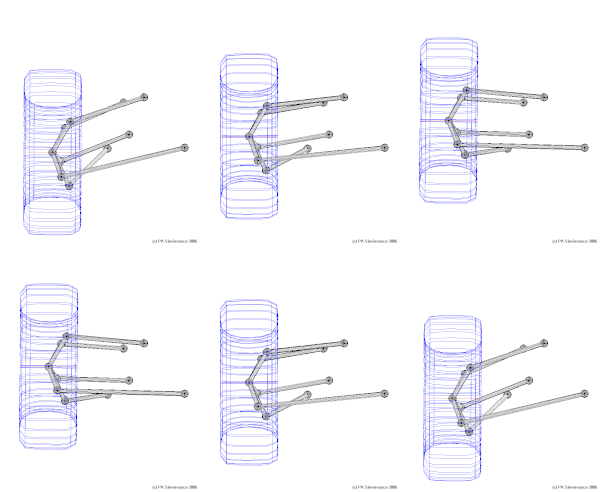
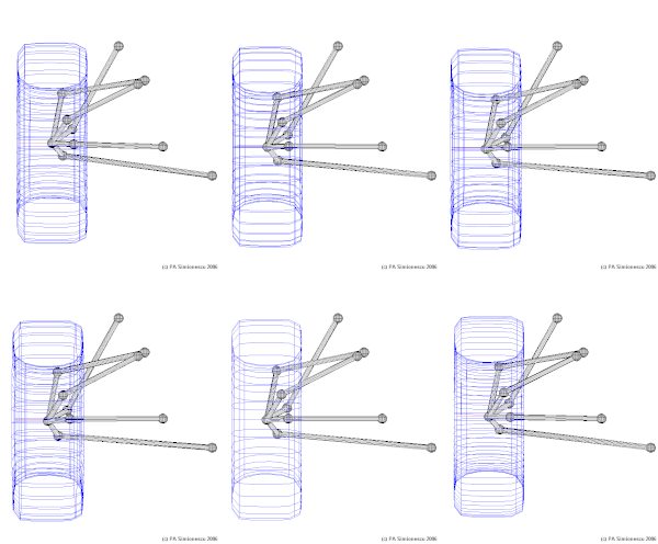
Typically each arm has a spherical joint (ball joint) or rubber bushing at each end. Consequently, they react to loads along their own length, in tension and compression, but not in bending. Some multi-links do use a trailing arm, control arm or wishbone, which has two bushings at one end.
On a front suspension one of the lateral arms is replaced by the tie-rod, which connects the rack or steering box to the wheel hub.
The solid axle multi-link system is another variation of the same concept, and offers some advantages over independent multi-link, as it is significantly cheaper and less complex to build, offering good mechanical resistance and excellent reliability with very similar benefits.
Layout
In order to simplify understanding, it is usual to consider the function of the arms in each of three orthogonal planes:
- Top view:
The arms have to control toe/steer and lateral compliance. This needs a pair of arms longitudinally separated.
- Front view:
The arms have to control camber, particularly the way that the camber changes as the wheel moves up (into jounce, or bump) and down into rebound or droop.
- Side view:
The arms have to transmit traction and braking loads, usually accomplished via a longitudinal link. They also have to control caster. Note that brake torques also have to be reacted - either by a second longitudinal link, or by rotating the hub, which forces the lateral arms out of plane, so allowing them to react 'spin' forces, or by rigidly fixing the longitudinal link to the hub.
- Solid axle suspension
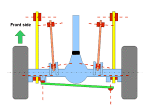
- When used in a solid axle suspension the multi-link system use the lower arms to control forward and backward motion, and the upper arms to control forward and backward rotation. This rotation is present under acceleration and braking.
Advantages
Multi-link suspension allows the auto designer the ability to incorporate both good ride and good handling in the same vehicle.
In its simplest form, multi-link suspension is orthogonal—i.e., it is possible to alter one parameter in the suspension at a time, without affecting anything else. This is in direct contrast to a double wishbone suspension, where moving a hardpoint or changing a bushing compliance will affect two or more parameters.
Advantages also extend to off-road driving. A multi-link suspension allows the vehicle to flex more; this means simply that the suspension is able to move more easily to conform to the varying angles of off-road driving. Multi-link-equipped vehicles are ideally suited for sports such as desert racing. In desert racing, the use of a good sway bar is needed to counter body roll.
The benefit of the triangulated and double-triangulated arrangement is that they do not need a panhard bar. The benefits of this are increased articulation and potential ease of installation.
Multi-link for solid axle offers a benefit over the independent multi-link in that it is significantly cheaper and much less complex to build.
Disadvantages
Multilink suspension is costly and complex. It is also difficult to tune the geometry without a full 3D computer aided design analysis. Compliance under load can have an important effect and must be checked using a multibody simulation software.
Gallery
Source:[4]
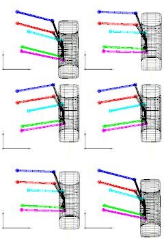 5-link rear wheel suspension mechanism (front view)
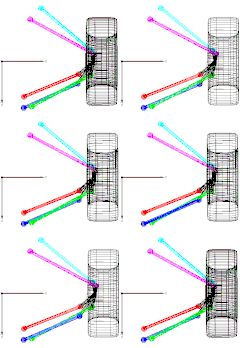 5-link rear wheel suspension mechanism (top view)
 5-link suspension mechanism with rack-and-pinion steering input (front view)
 5-link suspension mechanism with rack-and-pinion steering input (top view)
See also
References
- Bastow, D. (1970) Suspension ad Steering, Automobile Engineer, 8 May 1970, 217–231.
- von der Ohe, M. (1984) Independent Wheel Suspension, US Pat. 4,444,415, Filed Dec. 23, 1981
- von der Ohe, M. (1983) Front and Rear Suspension of the New Model W201, SAE technical Paper 831045.
- Simionescu, P.A. (2014). Computer Aided Graphing and Simulation Tools for AutoCAD Users (1st ed.). Boca Raton, Florida: CRC Press. ISBN 978-1-4822-5290-3.
- Adams, H. (1993). Chassis Engineering. New York, New York, Penguin Putnam.
- Milliken, W.F., Milliken, D. (2002). Chassis Design: Principles and Dynamics, SAE International.