Galvanic isolation
Galvanic isolation is a principle of isolating functional sections of electrical systems to prevent current flow; no direct conduction path is permitted.[1][2]


Energy or information can still be exchanged between the sections by other means, such as capacitive, inductive, radiative, optical, acoustic, or mechanical coupling.
Galvanic isolation is used where two or more electric circuits must communicate, but their grounds may be at different potentials. It is an effective method of breaking ground loops by preventing unwanted current from flowing between two units sharing a ground conductor. Galvanic isolation is also used for safety, preventing accidental electric shocks.
Methods
Transformer
Transformers are probably the most common means of galvanic isolation. They are almost universally used in power supplies because they are a mature technology that can carry significant power. They are also used to isolate data signals in Ethernet over twisted pair.[3] Transformers couple by magnetic flux. Except for the autotransformer, the primary and secondary windings of a transformer are not electrically connected to each other. The voltage difference that may safely be applied between windings without risk of breakdown (the isolation voltage) is specified in kilovolts by an industry standard. The same applies to magnetic amplifiers and transductors. While transformers are usually used to step up or step down the voltages, isolation transformers with a 1:1 ratio are used mostly in safety applications while keeping the voltage the same.
If two electronic systems have a common ground, they are not galvanically isolated. The common ground might not normally and intentionally have connection to functional poles, but might become connected. For this reason isolation transformers do not supply a GND/earth pole.
Opto-isolator
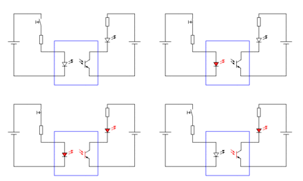
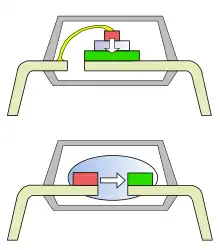
Opto-isolators transmit information by modulating light. The sender (light source) and receiver (photosensitive device) are not electrically connected. Typically they are held in place within a matrix of transparent, insulating plastic or within an integrated circuit. Optical isolation is generally very limited in power capacity, but it can carry very high speed data signals. A common use is for the feedback signal in a switching power supply, with the actual power transmitted through a high frequency transformer.
Capacitor
Capacitors allow alternating current (AC) to flow, but block direct current (DC); they capacitively couple AC signals between circuits that may or may not be at different DC voltages.
Although isolated power is usually done with a transformer, it can also be done with capacitors and a H-bridge driver when the constraints of size and cost favor capacitors.[4] Where capacitors are used for isolation from power supply circuits, they may carry special ratings to indicate they cannot fail in a short-circuit, possibly connecting a device to high voltage or presenting an electrical shock hazard. Ideally, where shock hazard safety is required, either other means of isolation should be used in place of capacitors or its value should be properly calculated as per safety standards, as there is always a current flow through capacitor depending on its value, when connected in any AC circuit in series configuration.
Hall effect
Hall-effect sensors allow an inductor to transfer information across a small gap magnetically. Unlike opto-isolators they do not contain a light source with a finite life, and in contrast to a transformer based approach they do not require DC balancing.
Magnetoresistance
Magnetocouplers use giant magnetoresistance (GMR) to couple from AC down to DC.
Relay
In a relay, the control signal energizes a coil that produces a magnetic field that pulls on an electrically isolated armature with switching contacts. The switching contacts may be normally closed (opening when the coil is energized) or normally open (closing when the coil is energized). Relays do not transmit power like a transformer, but relatively little coil power can control a much higher power circuit, making them a kind of amplifier. They are very widely used for control applications where the two sides operate at different voltages or otherwise require galvanic isolation. Large relays can switch very high currents, but they are limited in speed and reliability by their mechanical nature. One increasingly common application is in EVSE (Electric Vehicle Supply Equipment) where a high power relay energizes the supply cable only when it is securely connected to the vehicle and both ends are ready to transfer power.
Applications
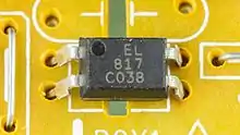
Optocouplers are used within a system to decouple a function block from another connected to the power grid or other high voltage, for safety and equipment protection. For example, power semiconductors connected to the line voltage may be switched by optocouplers driven from low-voltage circuits, which need not be insulated for the higher line voltage.
Transformers allow the output of a device to "float" relative to ground to avoid potential ground loops. Power isolation transformers increase the safety of a device, so that a person touching a live portion of the circuit will not have current flow through them to earth. Power sockets intended for electric razor supply may use an isolation transformer to prevent an electric shock if the razor should be dropped into water, although a ground fault circuit interrupter provides comparable protection for low- and high-power appliances.
See also
- Galvanic corrosion#Preventing galvanic corrosion, a potential benefit of galvanic isolation
- History of electrochemistry
- Luigi Galvani
References
- John Huntington Show Networks and Control Systems: Formerly Control Systems for Live Entertainment 2012 ISBN 0615655904, page 98
- "Description of Galvanic Isolation". Schneider Electric. Retrieved 2019-03-29.
- "Isolated Power Using Capacitors". Analog Devices. 2007. Archived from the original on 2023-01-29. Retrieved 2023-09-21.