House-built engine
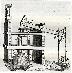
A house-built engine is a stationary steam engine that is built into an engine house, such that it uses the masonry of the engine house as an integral part of the support of the engine.[1]


Beam engines

.jpg.webp)
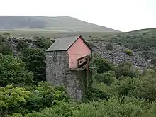
Most house-built engines were early beam engines. A 'bob wall'[2] in the engine house supported the pivot axle of the beam or 'bob'.[3] This wall could be an internal wall, with both ends of the beam inside the house, but it was commonly the end wall of the house and so the beam projected to the outside. For a heavy beam, the bob wall was required to be extremely substantial. Early engines were used for pumping mines or wells, so as well as the weight of the beam, the house had to also support the weight of the long pump rod, reaching down to the depths of the mine.[4]
Beam engines appeared during the 18th century. The only technologies at this time that could support the weight of an engine's beam were masonry and timber-framing, as the work of either shipwrights or millwrights. Cast iron was not yet a structural material, or capable of being worked at this scale. Wrought iron was too expensive to be used in such sizes.
After the early beam engines, where the cylinder was mounted directly atop the boiler, the space inside the house of later beam engines was divided by floors. The 'bottom chamber' contained the base of the cylinder, the lower valves and the valvegear. This was the main working chamber and was where the engine driver would spend most of their time.[5] Above this, a floor or partial floor and the 'top chamber' provided a working space for access to the valves or 'nozzles' at the top of the cylinder. This was used mostly for intermittent access to lubricate bearings etc. Often the floor did not span the full length of the house and formed a gallery above the bottom chamber. These floors and stairways were often fitted with woodwork and banisters of the highest quality. Similarly the 'beam chamber' at the top of the house provided access to the beam's bearings. Where the beam extended through the end wall of the house, two small outdoor platforms on either side of the beam gave access from the beam chamber to each side of the beam and the bearings for the pump shaft.[5] A final chamber was beneath the floor of the bottom chamber. This contained the air pump and regulating cataract. It was so rarely visited that access was only by means of a trapdoor.
House-built vertical engines

Small vertical engines were also house-built. An engine of this type, from Sunnybank Mill, has been preserved near Darwen.[6]
Table engines
One of the first engines to avoid the need for house-building was the table engine, from around 1800. This vertical engine placed the cylinder above the crankshaft and the crosshead above that, with a return connecting rod. Although Sadler's first table engine was house-built, Maudslay's patent table engine sat the cylinder upon a cast iron table, giving the engine its name. This table was independent of the engine house. Provided that the floor was strong enough to support the weight of the engine and was reasonably level, these engines could be placed anywhere, without needing special houses to be built for them.
Such construction was also quicker to build on-site, as a pre-manufactured engine could be supplied by the engine maker in almost completed form. Skilled engine erectors were a rare resource, especially in remote mining areas, and the need to have them working on-site for long periods whilst a large house was constructed around the engine was often a cause of delays to an engine being completed.[7] Even with adequate labour, masonry construction is a slower process than delivery of machinery alone. Where brick foundations were constructed, it was recommended that at least fifteen days were allowed before the weight of the engine was placed onto them.[8]
Horizontal engines
With the development of the horizontal stationary engine in the mid 19th century, the requirements were no longer to support a single heavy beam but now to provide accurate alignment between the cylinders and crankshaft of a medium-speed engine.[9] These foundations were substantial, going down perhaps three-dozen courses of brickwork below the engine bed. Deep iron anchors were provided within the brickwork for the engine to be bolted down. Rough local stone was no longer rigid enough and so foundations were constructed of many layers of hard engineering brick, as this was cheaper and more easily available than a cut ashlar stone of equal rigidity.[10] As these engine ran at faster speeds than the beam engines, their vibration could also be higher requiring a foundation that could withstand such. Alignment between slideways and crankshaft depended upon the original care with which the foundation had been built.

The girder bed engine avoided some of this dependency by providing the engine with a single long bed casting that spanned the crankshaft and trunk guide. The bed was connected to its plinth by a number of short pillars.[10] Although this bed still required care during erection to avoid twisting by clamping it down too firmly to a misaligned foundation, it did simplify engine alignment and also reduced effects if the foundation settled in service.
Where high-speed steam engines were used, these small engines usually incorporated a single-piece cast iron bed. This could be supported by a single brickwork pier, without needed careful alignment by its masons.[10] Some engine makers, such as Robey & Co. of Lincoln, developed a distinctive form of cantilevered cast iron bed for their large medium speed engines that formed both the crosshead trunk guide and the crank bearings, thus permitting a similar single plinth foundation.[11]
Late beam engines
House building for beam engines continued into the 20th century.
One of the largest sets of engines installed in a single engine house were the six engines for pumping the completed Severn Tunnel in 1886. These had six beams, arranged radially around the tunnel shaft, and passing in two groups of three through a pair of internal walls, just above ground level.[12]
The last Cornish engine built, at Dorothea Quarry in 1905,[2] has a through-wall beam supported on a wall 5 ft 6in thick.
See also
References
- Crowley, T.E. (1982). The Beam Engine. Senecio Publishing. p. 3. ISBN 0-906831-02-4.
- Crowley (1982), p. 130.
- Crowley (1982), p. 44.
- Hills 1989, pp. 73–75.
- Woodall, Frank D. (1975). Steam Engines and Waterwheels. Moorland. pp. 29–30. ISBN 0903485354.
- Hayes, G. (1981). A Guide to Stationary Steam Engines. Moorland Publishing. pp. 60–61. ISBN 0-86190-020-0.
- Hills, Richard L. (1989). Power from Steam. Cambridge University Press. pp. 73–75. ISBN 0-521-45834-X.
- Hawkins, Nehemiah (1897). "Engine Foundations". New Cathechism of the Steam Engine (1904 ed.). New York: Theo Audel. p. 33.
- Hawkins, Cathechism, pp. 31–38.
- Hawkins, Cathechism, pp. 35–36.
- Southworth, P.J.M. (1986). Some Early Robey Steam Engines. P.J.M. Southworth. ISBN 0-9511856-0-8.
- Walker, Thomas A. (2004) [1888]. The Severn Tunnel. Stroud: Nonsuch Publishing. p. 132. ISBN 1-84588-000-5.
