Turbine
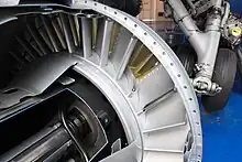
A turbine (/ˈtɜːrbaɪn/ or /ˈtɜːrbɪn/) (from the Greek τύρβη, tyrbē, or Latin turbo, meaning vortex)[1][2] is a rotary mechanical device that extracts energy from a fluid flow and converts it into useful work. The work produced can be used for generating electrical power when combined with a generator.[3] A turbine is a turbomachine with at least one moving part called a rotor assembly, which is a shaft or drum with blades attached. Moving fluid acts on the blades so that they move and impart rotational energy to the rotor. Early turbine examples are windmills and waterwheels.

Gas, steam, and water turbines have a casing around the blades that contains and controls the working fluid. Credit for invention of the steam turbine is given both to Anglo-Irish engineer Sir Charles Parsons (1854–1931) for invention of the reaction turbine, and to Swedish engineer Gustaf de Laval (1845–1913) for invention of the impulse turbine. Modern steam turbines frequently employ both reaction and impulse in the same unit, typically varying the degree of reaction and impulse from the blade root to its periphery. Hero of Alexandria demonstrated the turbine principle in an aeolipile in the first century AD and Vitruvius mentioned them around 70 BC.
The word "turbine" was coined in 1822 by the French mining engineer Claude Burdin from the Greek τύρβη, tyrbē, meaning "vortex" or "whirling", in a memo, "Des turbines hydrauliques ou machines rotatoires à grande vitesse", which he submitted to the Académie royale des sciences in Paris.[4] Benoit Fourneyron, a former student of Claude Burdin, built the first practical water turbine.
Operation theory

A working fluid contains potential energy (pressure head) and kinetic energy (velocity head). The fluid may be compressible or incompressible. Several physical principles are employed by turbines to collect this energy:
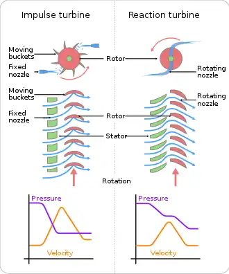
Impulse turbines change the direction of flow of a high velocity fluid or gas jet. The resulting impulse spins the turbine and leaves the fluid flow with diminished kinetic energy. There is no pressure change of the fluid or gas in the turbine blades (the moving blades), as in the case of a steam or gas turbine, all the pressure drop takes place in the stationary blades (the nozzles). Before reaching the turbine, the fluid's pressure head is changed to velocity head by accelerating the fluid with a nozzle. Pelton wheels and de Laval turbines use this process exclusively. Impulse turbines do not require a pressure casement around the rotor since the fluid jet is created by the nozzle prior to reaching the blades on the rotor. Newton's second law describes the transfer of energy for impulse turbines. Impulse turbines are most efficient for use in cases where the flow is low and the inlet pressure is high. [3]
Reaction turbines develop torque by reacting to the gas or fluid's pressure or mass. The pressure of the gas or fluid changes as it passes through the turbine rotor blades.[3] A pressure casement is needed to contain the working fluid as it acts on the turbine stage(s) or the turbine must be fully immersed in the fluid flow (such as with wind turbines). The casing contains and directs the working fluid and, for water turbines, maintains the suction imparted by the draft tube. Francis turbines and most steam turbines use this concept. For compressible working fluids, multiple turbine stages are usually used to harness the expanding gas efficiently. Newton's third law describes the transfer of energy for reaction turbines. Reaction turbines are better suited to higher flow velocities or applications where the fluid head (upstream pressure) is low. [3]
In the case of steam turbines, such as would be used for marine applications or for land-based electricity generation, a Parsons-type reaction turbine would require approximately double the number of blade rows as a de Laval-type impulse turbine, for the same degree of thermal energy conversion. Whilst this makes the Parsons turbine much longer and heavier, the overall efficiency of a reaction turbine is slightly higher than the equivalent impulse turbine for the same thermal energy conversion.
In practice, modern turbine designs use both reaction and impulse concepts to varying degrees whenever possible. Wind turbines use an airfoil to generate a reaction lift from the moving fluid and impart it to the rotor. Wind turbines also gain some energy from the impulse of the wind, by deflecting it at an angle. Turbines with multiple stages may use either reaction or impulse blading at high pressure. Steam turbines were traditionally more impulse but continue to move towards reaction designs similar to those used in gas turbines. At low pressure the operating fluid medium expands in volume for small reductions in pressure. Under these conditions, blading becomes strictly a reaction type design with the base of the blade solely impulse. The reason is due to the effect of the rotation speed for each blade. As the volume increases, the blade height increases, and the base of the blade spins at a slower speed relative to the tip. This change in speed forces a designer to change from impulse at the base, to a high reaction-style tip.
Classical turbine design methods were developed in the mid 19th century. Vector analysis related the fluid flow with turbine shape and rotation. Graphical calculation methods were used at first. Formulae for the basic dimensions of turbine parts are well documented and a highly efficient machine can be reliably designed for any fluid flow condition. Some of the calculations are empirical or 'rule of thumb' formulae, and others are based on classical mechanics. As with most engineering calculations, simplifying assumptions were made.

Velocity triangles can be used to calculate the basic performance of a turbine stage. Gas exits the stationary turbine nozzle guide vanes at absolute velocity Va1. The rotor rotates at velocity U. Relative to the rotor, the velocity of the gas as it impinges on the rotor entrance is Vr1. The gas is turned by the rotor and exits, relative to the rotor, at velocity Vr2. However, in absolute terms the rotor exit velocity is Va2. The velocity triangles are constructed using these various velocity vectors. Velocity triangles can be constructed at any section through the blading (for example: hub, tip, midsection and so on) but are usually shown at the mean stage radius. Mean performance for the stage can be calculated from the velocity triangles, at this radius, using the Euler equation:
Hence:
where:
- is the specific enthalpy drop across stage
- is the turbine entry total (or stagnation) temperature
- is the turbine rotor peripheral velocity
- is the change in whirl velocity
The turbine pressure ratio is a function of and the turbine efficiency.
Modern turbine design carries the calculations further. Computational fluid dynamics dispenses with many of the simplifying assumptions used to derive classical formulas and computer software facilitates optimization. These tools have led to steady improvements in turbine design over the last forty years.
The primary numerical classification of a turbine is its specific speed. This number describes the speed of the turbine at its maximum efficiency with respect to the power and flow rate. The specific speed is derived to be independent of turbine size. Given the fluid flow conditions and the desired shaft output speed, the specific speed can be calculated and an appropriate turbine design selected.
The specific speed, along with some fundamental formulas can be used to reliably scale an existing design of known performance to a new size with corresponding performance.
Off-design performance is normally displayed as a turbine map or characteristic.
The number of blades in the rotor and the number of vanes in the stator are often two different prime numbers in order to reduce the harmonics and maximize the blade-passing frequency.[5]
Types
- Steam turbines are used to drive electrical generators in thermal power plants which use coal, fuel oil or nuclear fuel. They were once used to directly drive mechanical devices such as ships' propellers (for example the Turbinia, the first turbine-powered steam launch[6]), but most such applications now use reduction gears or an intermediate electrical step, where the turbine is used to generate electricity, which then powers an electric motor connected to the mechanical load. Turbo electric ship machinery was particularly popular in the period immediately before and during World War II, primarily due to a lack of sufficient gear-cutting facilities in US and UK shipyards.
- Aircraft gas turbine engines are sometimes referred to as turbine engines to distinguish between piston engines.[7]
- Transonic turbine. The gas flow in most turbines employed in gas turbine engines remains subsonic throughout the expansion process. In a transonic turbine the gas flow becomes supersonic as it exits the nozzle guide vanes, although the downstream velocities normally become subsonic. Transonic turbines operate at a higher pressure ratio than normal but are usually less efficient and uncommon.
- Contra-rotating turbines. With axial turbines, some efficiency advantage can be obtained if a downstream turbine rotates in the opposite direction to an upstream unit. However, the complication can be counter-productive. A contra-rotating steam turbine, usually known as the Ljungström turbine, was originally invented by Swedish Engineer Fredrik Ljungström (1875–1964) in Stockholm, and in partnership with his brother Birger Ljungström he obtained a patent in 1894. The design is essentially a multi-stage radial turbine (or pair of 'nested' turbine rotors) offering great efficiency, four times as large heat drop per stage as in the reaction (Parsons) turbine, extremely compact design and the type met particular success in back pressure power plants. However, contrary to other designs, large steam volumes are handled with difficulty and only a combination with axial flow turbines (DUREX) admits the turbine to be built for power greater than ca 50 MW. In marine applications only about 50 turbo-electric units were ordered (of which a considerable amount were finally sold to land plants) during 1917–19, and during 1920-22 a few turbo-mechanic not very successful units were sold.[8] Only a few turbo-electric marine plants were still in use in the late 1960s (ss Ragne, ss Regin) while most land plants remain in use 2010.
- Statorless turbine. Multi-stage turbines have a set of static (meaning stationary) inlet guide vanes that direct the gas flow onto the rotating rotor blades. In a stator-less turbine the gas flow exiting an upstream rotor impinges onto a downstream rotor without an intermediate set of stator vanes (that rearrange the pressure/velocity energy levels of the flow) being encountered.
- Ceramic turbine. Conventional high-pressure turbine blades (and vanes) are made from nickel based alloys and often use intricate internal air-cooling passages to prevent the metal from overheating. In recent years, experimental ceramic blades have been manufactured and tested in gas turbines, with a view to increasing rotor inlet temperatures and/or, possibly, eliminating air cooling. Ceramic blades are more brittle than their metallic counterparts, and carry a greater risk of catastrophic blade failure. This has tended to limit their use in jet engines and gas turbines to the stator (stationary) blades.
- Shrouded turbine. Many turbine rotor blades have shrouding at the top, which interlocks with that of adjacent blades, to increase damping and thereby reduce blade flutter. In large land-based electricity generation steam turbines, the shrouding is often complemented, especially in the long blades of a low-pressure turbine, with lacing wires. These wires pass through holes drilled in the blades at suitable distances from the blade root and are usually brazed to the blades at the point where they pass through. Lacing wires reduce blade flutter in the central part of the blades. The introduction of lacing wires substantially reduces the instances of blade failure in large or low-pressure turbines.
- Shroudless turbine. Modern practice is, wherever possible, to eliminate the rotor shrouding, thus reducing the centrifugal load on the blade and the cooling requirements.
- Bladeless turbine uses the boundary layer effect and not a fluid impinging upon the blades as in a conventional turbine.

- Water turbines
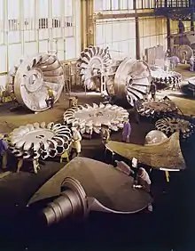
- Pelton turbine, a type of impulse water turbine.
- Francis turbine, a type of widely used water turbine.
- Kaplan turbine, a variation of the Francis Turbine.
- Turgo turbine, a modified form of the Pelton wheel.
- Tyson turbine, a conical water turbine with helical blades emerging partway down from the apex gradually increasing in radial dimension and decreasing in pitch as they spiral towards the base of the cone.
- Cross-flow turbine, also known as Banki-Michell turbine, or Ossberger turbine.
- Wind turbine. These normally operate as a single stage without nozzle and interstage guide vanes. An exception is the Éolienne Bollée, which has a stator and a rotor.
- Velocity compound "Curtis". Curtis combined the de Laval and Parsons turbine by using a set of fixed nozzles on the first stage or stator and then a rank of fixed and rotating blade rows, as in the Parsons or de Laval, typically up to ten compared with up to a hundred stages of a Parsons design. The overall efficiency of a Curtis design is less than that of either the Parsons or de Laval designs, but it can be satisfactorily operated through a much wider range of speeds, including successful operation at low speeds and at lower pressures, which made it ideal for use in ships' powerplant. In a Curtis arrangement, the entire heat drop in the steam takes place in the initial nozzle row and both the subsequent moving blade rows and stationary blade rows merely change the direction of the steam. Use of a small section of a Curtis arrangement, typically one nozzle section and two or three rows of moving blades, is usually termed a Curtis 'Wheel' and in this form, the Curtis found widespread use at sea as a 'governing stage' on many reaction and impulse turbines and turbine sets. This practice is still commonplace today in marine steam plant.
- Pressure compound multi-stage impulse, or "Rateau", after its French inventor, Auguste Rateau. The Rateau employs simple impulse rotors separated by a nozzle diaphragm. The diaphragm is essentially a partition wall in the turbine with a series of tunnels cut into it, funnel shaped with the broad end facing the previous stage and the narrow the next they are also angled to direct the steam jets onto the impulse rotor.
- Mercury vapour turbines used mercury as the working fluid, to improve the efficiency of fossil-fuelled generating stations. Although a few power plants were built with combined mercury vapour and conventional steam turbines, the toxicity of the metal mercury was quickly apparent.
- Screw turbine is a water turbine which uses the principle of the Archimedean screw to convert the potential energy of water on an upstream level into kinetic energy.
Uses
A large proportion of the world's electrical power is generated by turbo generators.
Turbines are used in gas turbine engines on land, sea and air.
Turbochargers are used on piston engines.
Gas turbines have very high power densities (i.e. the ratio of power to mass, or power to volume) because they run at very high speeds. The Space Shuttle main engines used turbopumps (machines consisting of a pump driven by a turbine engine) to feed the propellants (liquid oxygen and liquid hydrogen) into the engine's combustion chamber. The liquid hydrogen turbopump is slightly larger than an automobile engine (weighing approximately 700 lb) with the turbine producing nearly 70,000 hp (52.2 MW).
Turboexpanders are used for refrigeration in industrial processes.
See also
Notes
- "turbine"."turbid". Online Etymology Dictionary.
- τύρβη. Liddell, Henry George; Scott, Robert; A Greek–English Lexicon at the Perseus Project.
- Munson, Bruce Roy, T. H. Okiishi, and Wade W. Huebsch. "Turbomachines." Fundamentals of Fluid Mechanics. 6th ed. Hoboken, NJ: J. Wiley & Sons, 2009. Print.
- In 1822, Claude Burdin submitted his memo "Des turbines hydrauliques ou machines rotatoires à grande vitesse" (Hydraulic turbines or high-speed rotary machines) to the Académie royale des sciences in Paris. (See: Annales de chimie et de physique, vol. 21, page 183 (1822).) However, it was not until 1824 that a committee of the Académie (composed of Prony, Dupin, and Girard) reported favorably on Burdin's memo. See: Prony and Girard (1824) "Rapport sur le mémoire de M. Burdin intitulé: Des turbines hydrauliques ou machines rotatoires à grande vitesse" (Report on the memo of Mr. Burdin titled: Hydraulic turbines or high-speed rotary machines), Annales de chimie et de physique, vol. 26, pages 207-217.
- Tim J Carter. "Common failures in gas turbine blades". 2004. p. 244-245.
- Adrian Osler (October 1981). "Turbinia" (PDF). (ASME-sponsored booklet to mark the designation of Turbinia as an international engineering landmark). Tyne And Wear County Council Museums. Archived from the original (PDF) on 28 September 2011. Retrieved 13 April 2011.
- Wragg, David W. (1973). A Dictionary of Aviation (first ed.). Osprey. p. 267. ISBN 9780850451634.
- Ingvar Jung, 1979, The history of the marine turbine, part 1, Royal Institute of Technology, Stockholm, dep of History of technology
Further reading
- Layton, Edwin T. "From Rule of Thumb to Scientific Engineering: James B. Francis and the Invention of the Francis Turbine," NLA Monograph Series. Stony Brook, NY: Research Foundation of the State University of New York, 1992.