Izbash formula
The Izbash formula is a formula for the stability calculation of armourstone in running water.
The stability of granular material in flow can be determined by the Shields formula or the Izbash formula. The first is more suitable for fine grain material (such as sand and gravel), while the Izbash formula is more suitable for larger stone. The Izbash formula was developed by Sergei Vladimirovich Izbash. In general form, the formula [1]
- ... or ...


where:
- uc = flow rate in the vicinity of the stone
- Δ = relative density of the stone (= (ρs -ρw)/ρw) where ρs is the density of the stone and ρw is the density of the water
- g = acceleration of gravity
- d = diameter of the stone
The coefficient 1.7 is the experimental constant measured by Izbash. In fact, this constant contains two components, namely an effect for friction, inertia, etc. and a component that describes the turbulent character of the current. The use of the coefficient 1.7 is therefore only permitted in currents where the turbulence is locally generated by the roughness of the water building block. In other cases, this should be adjusted.
Derivation of the Izbash formula
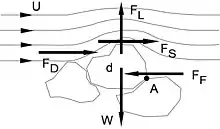
Izbash considered the forces on a stone in the current. These are three active forces and two passive forces. The active forces are the lift force FL, the friction force FS and the drag FD. The passive forces are the weight W and the resistance force FF. If the moment equilibrium is considered around point A, then FF disappears (because the arm is zero). The active forces can be written out as:
![{\displaystyle {\begin{matrix}F_{D}&={\frac {1}{2}}C_{D}\rho _{w}u^{2}A_{D}\\F_{S}&={\frac {1}{2}}C_{F}\rho _{w}u^{2}A_{S}\\F_{L}&={\frac {1}{2}}C_{L}\rho _{w}u^{2}A_{L}\end{matrix}}\quad {\Biggr ]}\quad F\sim \rho _{w}u^{2}d^{2}}](../I/8b077cd2b3fd868d255a30e99ec180316a001f97.svg)
The total active force is therefore proportional to ρwu²d². The remaining passive force is proportional to (ρs-ρw)g²d³. And if this is equal, it follows uc²=KΔgd. This formula can also formulated in the format as mentioned in the form as above the page; the coefficient is determined by measurements, and appears to be 1.7.
Calculation Example
Question: What stone size is needed to defend the bottom of a 1 m depth channel at an average flow rate of 2 m/s?
This can be easily determined by the formula rewriting the formula in a slightly different form and enter athe data. However, the Izbash formula requires the speed “near the stone”, which is not well defined. Practically, a value of approx. 1 times the stone diameter above the protection layer can be taken. With a normal logarithmic flow profile, this is about 85% of the average velocity. This gives a stone diameter of 6.3 cm (the formula of Shields gives 6.5 cm in this case).
Restrictions
The formula uses the speed near the stone. It is difficult to determine, especially in smooth soils and larger water depths. In these cases, Shields formula is preferable.
Pilarczyk
Because the coefficient of 0.7 is very common, Pilarczyk changed the formula around 1985, making it more specific. [2] This extension takes the form of:

in which:
- Φ = stability parameter, adapts the formula for different types of constructions:
- φ = 1.25 at the end of a single layer of rock
- φ = 1.0 at the end of a bed protection
- φ = 0.75 for a two-layer rock bed protection
- φ = 0.50 for continuous bed protections
- the most conservative value is 1.5.
- Ψ = Shields parameter, this parameter is for dumped rock 0.035 and for placed rock 0.05
- Kt = turbulence factor
- kt = 0.67 for low-turbulent flow
- kt = 1.0 for normal turbulence
- kt = 1.5 in river bends
- kt = 2.0 - 2.5 in sharp river bends (with a radius of < 5 times river width)
- kt = 3.0 for high turbulence flow (propeller race)
- kt = 4.0 extreme high turbulence (propeller race at moored ships)
- Kh = depth factor
- Usually , N is 1 to 3
- kh for a not fully developed velocity profile:
- Ks= steepness factor
- The value of Ks is either equal to or (see below).
 Slope effect of a current


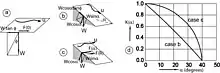
The destabilising effect of a slope can be split into two components. In the explanation below, φ is the slope of natural tallow of the soil material. There is a component along the slope (W sinα), which reduces the effective weight perpendicular to the slope (Wcosα). If the inclination is in the same direction as the current (Figure b), then the strength F(αperpendicular) = Wcosα tanφ – Wsinα (Note: If the current is the other way, the stone is more stable and F=Wcosα tanφ+ Wsinα.) The relationship between F(α) and F(0) gives the reduction factor for strength:
- For a transverse slope at an angle α the same procedure can be followed, see figure c. but now the components have to be added as vectors.


Figure d shows both reduction factors for a value of φ=40 degrees.
Because a depth factor Kh is included in this version of the Izbash formula, the average velocity above the stones can be taken for the speed, the original Izbash formula was that the speed was “near to the stone”, which was not well defined.
Effect of turbulence
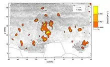
Turbulence also has a major effect on stability. Turbulent vortices give locally a high speed at the stone, so on one side there is lift force, and on the other side there is no lift force. As a result, the stone is thrown out of the bed, as it were. See also the detail drawing. In this example, the stone lies on the coordinate (0,0). On the left is a relative speed, so a lift force up, on the right is no relative velocity, so no lift force. So there is a right-turning moment on the stone which turns it out (together with the normal lift force of the main current). This shows why at a certain speed not all stones move directly, but only when a “appropriate” vortex passes.
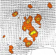
These figures are measurements of the flow rate in a vertical plane above a stone. The flow rate is from left to right. Shown is the speed after deduction of the average speed, i.e. actually the u and the v (for explanation of this, see the main article on turbulence modelling.
The effect of turbulence on stability is especially great if the size of the turbulent vortices is in the same order of magnitude as the size of the stone.
It is possible to adjust the Izbash formula so that the effect of turbulence can be taken into account more explicitly.[4] A stone on the ground does not move until the total speed (i.e. the average velocity plus the extra velocity due to the turbulent vortices) exceeds a certain value. Research has shown that this extreme velocity is about is, where is the standard deviation of the velocity and r is the relative turbulence. In the original Izbash formula, the coefficient 1.7 contains a part that is responsible for the turbulence. The Izbash formula can be rewritten as:


![{\displaystyle \Delta d=0,7{\frac {u^{2}}{2g}}=c_{iz}{\frac {\left[u(1+3r)\right]^{2}}{2g}}}](../I/372870f8ac628b71b617861130d09dc0456cfb37.svg)
For turbulence caused by bed roughness one can assume a relative turbulence value of r=0.075, which in the above formula leads to =0.47. This creates an Izbash formula with an explicit parameter for turbulence:

![{\displaystyle \Delta d=0,47{\frac {\left[u(1+3r)\right]^{2}}{2g}}}](../I/7b68c73a4f58e28fab0289a74876de55ac2bb9d7.svg)
This makes it possible to use the Izbash formula in cases where turbulence is not caused solely by bed roughness, for example in flow caused by ships and ship screws. For ships sailing in a (small) canal, there is a strong return flow along the ship with increased turbulence. The value of the relative turbulence in this case is r = 0.2. For turbulence due to a propeller flow it is recommended r = 0.45.[5] Because the relative turbulence is quadratic in the formula, it is clear that in the case of a propeller flow a significantly heavier rock size for.bed protection is required than in the case of “normal” flow.
For “non-standard” cases one can apply a turbulence model, e.g. a k-epsilon model, to calculate the value of r. This can then be introduced in the above-mentioned modified Izbash formula to determine the required stone size.
References
- General reference: CIRIA, CUR, CETMEF (2007). The rock manual : the use of rock in hydraulic engineering. London: CIRIA C683. p. 1268. ISBN 9780860176831.
{{cite book}}: CS1 maint: multiple names: authors list (link)
- Footnotes
- Izbash, Sergey Vladimirovich (1935). Construction of Dams by Dumping Stones into Flowing Water: (original title: Постройка плотин наброской камня в текущую воду) (in Russian). Leningrad: Scientific Research Institute of Hydrotechnics. p. 138.
- Pilarczyk, Krystian (1998). Dikes and revetments, chapter 16. Delft, Netherlands: Balkema. ISBN 9789054104551.
- Hofland, Bas (2005). Rock & Roll, Turbulence-induced damage to granular bed protections. Delft: TU Delft. p. 241. ISBN 9789090201221.
- Schiereck, Gerrit Jan; Verhagen, Henk Jan (2012). Introduction to bed, bank and shoreline protection. Delft: Delft Academic Press. pp. 70–75. ISBN 978-90-6562-306-5. Archived from the original on 2019-04-13. Retrieved 2023-05-20.
- Verheij, H.J. (1988). Aanpassing van dwarsprofielen van vaarwegen (in Dutch). Delft: Delft Hydraulics. p. M1115/XIX.