La Vicaria Arch Bridge
La Vicaria Bridge is a through arch bridge that spans the Segura River, where it meets La Fuensanta Reservoir near Yeste, in the province of Albacete, Spain. It forms part of a future road that will join Yeste with Letur and the neighbouring area to the east. The bridge has 2 vehicle lanes and 2 sidewalks.
La Vicaria Arch bridge | |
|---|---|
 | |
| Coordinates | 38.3528°N 2.2579°W |
| Crosses | Segura River |
| Locale | Yeste, Albacete |
| Characteristics | |
| Design | Tied arch bridge |
| Total length | 260 metres (850 ft) |
| Width | 11 metres (36 ft) |
| Longest span | 168 metres (551 ft) |
| Clearance above | 40 metres (130 ft) above the river |
| History | |
| Opened | August, 2007 |
| Location | |
Introduction
La Fuensanta Reservoir and the River Segura divide the municipal district of Yeste into two parts. This village is the main town of an isolated and mountainous region in the southern part of the province of Albacete. The bridge provides direct access to the village from the east (previously it had only been accessible from the north) and, as a result of avoiding travelling around the large reservoir, reduces the journey time by 50 minutes.
The owner of the bridge, the Confederación Hidrográfica del Segura[1] (Segura Water Authority, that includes irrigation districts), decided to construct the bridge in order to resolve the old transportation problems of the Yeste population and to act as a landmark. As a result, they employed Ferrovial-Agromán as the builder and final designer. Ferrovial-Agromán gathered, and expanded on, previous ideas in order to find a complete solution that included an innovative construction process.
Description
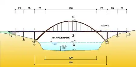
The structure is a 168 m through arch bridge with approaching spans, taking advantage of the natural valley's morphology and the width of the reservoir at this point. The foundations of the arches rest on the limestone rock on both hillsides at the reservoir's high water level.

| La Vicaria Arch | Main Parameters |
|---|---|
| Total length (m) | 260 |
| Spans length (m) | (20+25+170+25+20) |
| Span / Rise (arch) | 3.4 |
| Span / Depth section (crown of arch) | 140 |
| Span / Depth section (base of arch) | 70 |
| Span / Depth section (deck) | 134 |
Deck
The deck is a continuous composite structure, consisting of concrete and weathering steel, simply supported on piers using neoprene bearings and rigidly connected to the arches at their intersection. Its cross-section is made up of two longitudinal steel box beams of 1 m depth and cross brace each other by flange steel beams. The deck is in-situ concreted on precast slabs which work with the slab in service.

Arches
The arches span 168 m, of which 120 m is over the deck, with a 10° inward incline towards the deck. The rise is 49 m, of which 25 m is over the deck, and are crossed braced by six cross-beams with a similar outer section to that of the arch.
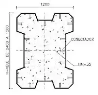
The arch sections are quasi-rectangular steel tubes, filled with self compacting concrete, formed by 4 metal plates that are folded and welded at their ends. Their width is constant along the length of the arch and their depth varies from 2.4 m to 1.2 m.
The deck is connected to the arch by 12 pairs of vertical hangers at the arches and the deck intersection point, 60 m from the centre of the bridge, rigidly joined by a cross brace.
Each arch is embedded at the ends in a reinforced concrete block (the smallest being 6 m long, 7 m high and 5 m wide) connected by means of a joint of 28 steel bars until reaching the suitable foundation surface in the rock. In order to avoid transmitting transversal force to the rocky mass, the blocks on each bank have been cross braced to each other using a reinforced concrete brace, which balances the reactions of the 2 arches on each bank.
Piers
The piers are Y-shaped and in-situ concrete. The deck connects to each pier via a cross-beam that connects two longitudinal beams. This arrangement allows the visual continuity of the depth section of the deck along the bridge, emphasizing its slenderness.
Construction Stages
Steel Structure
The through arch steel structure (arch + deck) was divided into 3 partial steel substructures:
Tied Arch
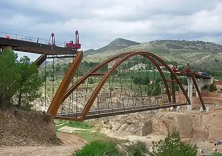
A temporary platform was erected at the bed of the reservoir on which the central 120 m of the steel deck was assembled. Falsework towers were erected at the same position as the final hangers and each semi-arch was divided into three steel transport segments, supported on the towers and joined to each other as well as to the ends of the deck. After the hangers were located, the shoring was removed; loading the steel tied arch bridge.

Approaching spans and Cantilevers
The steel structure of the approaching spans of each bank were assembled on the ground and then placed, using a crane, on the piers. The steel bases of the arches (the distance from the arch's basement to the deck's intersection) were then placed in one single operation with a crane (33m in cantilever) and embedded into the foundation block. Having positioned the two pieces of the arches on one bank, they were joined at the top by means of a steel brace placed with a crane. Consequently, the crane placed the steel structure of the deck from pier to the arch-deck section.
Lifting
Once the three self-supporting partial steel structures had been built, the bowstring arch was raised into position, joining the three partial arches.
The side walls of the abutments contain retaining prestressed tendons which were used to fix the deck to the abutment during the lift. Once tensioned, the 470 ton bowstring was raised 40 m, using a lifting machine, to its final level, taking just eight hours by subcontractor ALE Lastra. The arches were then joined, the tendons in the abutments released and the decks connected.
Concreting
Arches
In order to ensure that the balance of the loads applied to the arches was maintained throughout the curing process, the arches were filled with concrete in two phases. Each arch was divided into 5 m long watertight modules, filled alternately in each phase with self-compacting concrete.
Deck
Once the arch was rigid, precast slabs were situated over the steel beams of the deck and then it was concreted from the centre towards the exterior in order to reduce strains and forces acting during construction.
Finishes
After the entire dead load of the bridge was loaded, dampers and shock absorbers were installed in order to reduce the vertical deflections produced by asymmetric live loads in the arch and to allow slow deflections in the deck due to thermal and rheological actions.
The bridge was completed in August 2007.
Gallery of images
 Assembling the bowstring.
 Assembling the tied arch.
 Assembling cantilever arches.
 Concreting of arches.
 Concreting of deck.
 Finished.
References
- "Confederación Hidrográfica del Segura". Archived from the original on 2006-07-17.
3D model of the bridge in Sketchup
Improving Infrastructure Worldwide, IABSE Symposium, Weimar, 19–21.09.2007