Tank steering systems
Tank steering systems allow a tank, or other continuous track vehicle, to turn. Because the tracks cannot be angled relative to the hull (in any operational design), steering must be accomplished by speeding one track up, slowing the other down (or reversing it), or a combination of both. Half-track vehicles avoid this by combining steerable wheels and fixed-speed tracks.
Early steering systems were adopted from tracked work vehicles, generally using a clutch to reduce power to one track, causing it to slow down. These designs have numerous problems, notably when climbing hills or running at high speed, as the reduction in power causes the overall speed to slow. Delivering power to both tracks while turning them at different speeds is a difficult design problem.
A series of more advanced designs were introduced, especially through World War II, that maintained power to both tracks during steering, a concept known as regenerative steering. Some also allowed one track to move forward while the other reversed, allowing the tank to spin in place, a concept known as neutral steering. The first really successful system was the British double differential design of 1924, which was copied by both the United States and Germany.
Most modern Western designs use a variation of the double differential, while Soviet designs preferred to use two separate transmissions in a single housing. Systems using electric motors with variable speed controls have been tried on a number of occasions, but have not entered widespread service.
Dual drive
One solution to the steering problem is to use two separate drivetrains, each driving one track. This maintains power to both tracks while steering, produces a wide range of turning circles, and even allows one track to be reversed while the other moves forward, allowing the tank to turn in place. This may be combined with brakes to further control the steering radius.[1]
The obvious disadvantage to this design is the cost and complexity of two drive trains, and the increased maintenance load that implies. Another is that if one engine fails, the other cannot be used to drive both tracks. Both of these problems were greatly reduced in the case of steam power, where the majority of the engine in terms of size and weight is the boiler, and the cylinders that extract that power are much smaller in comparison. It can also provide variable output by controlling the amount of steam sent to each cylinder. It is much more complex when used with internal combustion engines.[1]
A less obvious problem is that it is very difficult to keep such a vehicle moving in a straight line. Although a governor can be used to ensure the two engine speeds are similar, loads on the tracks will not be the same as it moves over different terrain, causing the more heavily loaded track to slow and the tank to turn in that direction. This will cause the tank to wander when moving over uneven ground. This is not an issue at very low speeds, and the system is sometimes used on bulldozers and other tracked construction vehicles. For tanks, considerable driver skill and constant adjustment are needed, even at the relatively low speeds seen on early designs.[1]
Examples of true twin-drive systems are not common, but have existed through much of tank history. Examples include the World War I-era British Whippet medium tank.
Twin transmission, or geared steering

A simple step up from the dual-drive concept is to use a single engine and split the power output into two transmissions. Steering is accomplished by changing the gear on one track and not the other. This reduces the complexity of the dual-drive system when combined with a modern engine. It also introduces a new behaviour; additional load on one track causes the other to slow as well. This is actually an improvement over the dual drive solution, as it causes the entire tank to slow, not turn towards the loaded track.[2]
The downside to this approach is that high-power transmissions are failure-prone devices, especially in the World War II era. They are also complex and time-consuming devices to build and repair. Although it eliminates a second engine, compared to the dual-drive concept, it is still relatively complex compared to the solutions that follow.[2]
Dual-drive systems were widely used since the earliest days of tracked vehicles, including the Holt 75 tractor that saw widespread use in World War I.[3] The Japanese adopted the concept in 1925, and all their subsequent tanks through World War II used this. The British also continued to use it on light tanks like the Covenanter and Crusader of the early war period. The Czech LTH also adopted the system, seeing service with the Germans as the Panzer 38(t).[2]
The Soviets introduced this system for their KV-13 experimental tank, and this led to its use in the IS tank family. Later versions introduced more gears to produce multiple turning radii, including reversing one track. The T-64 introduced a new model with seven speeds, and this basic system has been used on the T-72, T-90 and Chinese Type 98.[2][4]
Clutch braking
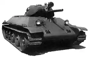
The simplest single-engine steering system in mechanical terms, and almost universally used on early tank designs, was the combination of a brake and a clutch connected to steering controls. The controls were normally a pair of vertical handles, one for each track. Pulling on a handle disengaged the clutch, releasing that track and causing it to slow down. Further motion of the handle increasingly applied the brake to that track, allowing the turning circle to be adjusted.[2]
The main disadvantage of this design is that when steering is applied the engine power is removed from the track. This makes the tank slow down, even if the brake is not applied. If the tank is climbing, or in soft terrain, forward motion may stop entirely. Another disadvantage is that the brakes constantly dissipate vast amounts of heat when steering, which is very power-inefficient. The brakes suitable to steer a large vehicle are also impracticably large.[2]
Clutch braking was introduced by the French in 1916 during World War I. Most light tanks used it through the 1920s and 30, as well as some larger tanks like the British experimental Vickers Independent and Soviet T-35. The last major designs to use it were the Soviet T-34 and German Panzer III and Panzer IV.[2]
Differential braking
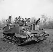
Differential braking (or braked differential) systems remove the clutches on the track and add a differential on the transmission output. The differential allows the tracks to turn at different speeds while remaining powered. Steering is then accomplished by slowing one track with a brake. The advantage to this design is that power is maintained to both tracks even while steering is taking place. Another advantage is outright simplicity; the steering system connects directly to the brake and nothing else, producing a very simple mechanical arrangement.[2]
The main disadvantage, like the clutch braking system, is that steering dissipates heat through the brakes. Unlike the clutched system, however, in this case all turning requires braking. This can be used on lighter tanks, but the amount of kinetic energy in larger tanks makes the required brakes impractically large. Another disadvantage is that the differential will allow the tracks to turn at different speeds no matter what the cause may be. This may be the application of braking, but also occurs as the tank travels over terrain; if one side of the tank enters softer terrain and slows down, the tank will naturally turn towards that side. Forward momentum tends to offset this effect, so it is mainly a problem at low speeds.[2]
Differential braking actually predates clutch braking on tracked vehicles, having been initially introduced by Richard Hornsby & Sons in 1905 on the world's first tracked vehicle. Clutch braking became popular only because of its mechanical simplicity. Differential braking could be found on many smaller tanks, especially in the pre-World War II era. British tanks began using them during World War I, and continued into World War II. One common example was the Bren Carrier.[2]
Controlled differential
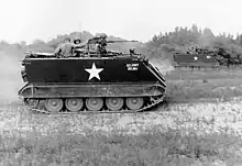
Differential braking systems are essentially an epicyclic transmission with a single fixed gear ratio transmitted through idler pinions. The controlled differential adds an extension to the rack holding the idlers, and puts a conventional brake on that extension. With the brake applied, the idlers are locked and the system works like a conventional epicyclic. When the brake is released, the idlers spin, reducing the speed of rotation on that side. This causes the output on that side to slow down by a fixed amount.[2]
The advantage to this design is that the brake is not being applied to slow the vehicle, it is simply clutching the second set of gears in or out. This means it does not dissipate energy, except in the brief period it is being applied or released. Smoother steering can be accomplished by partial application of the brake, but then it begins to dissipate energy like the braked differential. The main disadvantage is that there is only one turning radius. Like the standard differential solution, these systems are also subject to self-turning when travelling over terrain.[2]
The system was invented by Cleveland Tractor Company in 1921, and is sometimes known by the trademarked name Cletrac Differential. It was used by most French tanks in the inter-war era, as well as on the German Grosstraktor. It was most common on US designs, used on all light and mediums from 1932 until the end of World War II. Later uses included the French AMX 13, Japanese Type 61, and the widely produced US M113 APC.[2]
Double differential
.2.jpg.webp)
The more complex double differential system is similar to the controlled differential in basic concept, in that it controls the speed of the tracks by controlling the rotation of the idlers. However, in this case two complete differentials are used, one for each track, and the idlers are controlled not by a brake, but a second power shaft, the steering shaft.[2]
Normally the steering shaft is connected to the engine directly, instead of the output from the transmission. This means it spins at a relatively narrow range of RPM compared to the main drive shaft. The steering shaft is split into two output shafts through a clutch system that allows the outputs to spin forward, backward, or not at all. An idler reverses the direction on one side, so they always spin in opposite directions.[2]
With the clutch off, so the shaft does not spin, the idlers in the two differentials are fixed in place. This is just like the controlled differential with the brake on. When the steering clutch is engaged, the shaft spins one of the idler sets forward and the other backward, causing one track to speed up and the other to slow down.[2]
Since the speed difference of the two tracks is independent of the gearbox selection, this makes the steering effect less pronounced at higher speeds; this means the tank has a longer turning radius at higher speeds, which is generally what is wanted. The system, however, produces only one radius for any given gearbox selection.[5]
The system is fully regenerative: all of the engine's power reaches the track either through the main driveshaft or the steering system; none of the energy is being lost to brakes or clutches. Additionally, since power is fed around the transmission to the steering system, in some designs the tank can be turned or even pivoted in place even when the main gearbox is not engaged, a function known as neutral steering. The limitation on this feature is the strength of the steering shaft, which has to be strong enough to move the tank if this feature is desired, but otherwise can be made lighter if this is not needed.[5]
Double differentials were first used in experiments in France starting in 1921, and found on many heavy tanks of World War II, including the German Tigers. The addition of a continuously variable output using a hydrostatic transmission was used on the Char B1, providing smooth changes in turning radius that eliminated the system's main drawback. The low efficiency of this system meant it was not widely used, but rapid improvement in hydrodynamic fluid couplings made it common in the post-war era. Most Western tank designs since the 1960s have used a variation on this design, notably the M60 Patton and M1 Abrams.[5]
Merritt–Brown triple differential
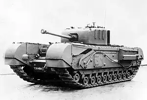
This system was devised by Dr. H. E. Merritt, Director of Tank Design at Woolwich Arsenal, and manufactured by David Brown Ltd.
The triple differential is a modification to the double differential, replacing the steering clutches with a single braked differential similar to a controlled differential. This third differential produces any desired output speed in the steering shaft, compared to the double differential where the speed of the shaft is fixed. This output drives the steering idlers of an otherwise unchanged double differential, producing continuously variable steering. It has all the advantages of the double differential, while the only disadvantage is that the brake on the third differential dissipates some energy while slipping, but this is dependent only on the amount of energy being used to steer the vehicle, not the total energy being delivered to the tracks.[5]
The triple differential was used primarily on war-time and post-war British tanks, first on the Churchill tank and later on the Cromwell tank and its follow-on designs. It gave these designs unparalleled maneuverability and the ability to climb that was not matched by other designs until well into the Cold War. The basic version continued to be used on British designs until the TN 10 of the Conqueror and the TN 12 on the Chieftain. This system is generally not used today, in favour of improved hydrodynamic transmissions in the double differential, starting with the transmission in the Challenger.[5][6]
Maybach double differential
.jpg.webp)
The Maybach system is essentially a simplified version of the double differential, or more accurately in mechanical terms, a double controlled differential. It replaces the double differential's forward and reverse steering shaft and clutch system with a single shaft that spins in one direction, and brakes on the idlers. Like the controlled differential, the brakes are normally applied to keep the idlers fixed. The steering inputs release one or the other brake to cause the idler to spin and that track to slow. Unlike the full double differential, the other side is not sped up so the system is not fully regenerative, and since both idler sets spin in the same direction, it does not offer neutral steering. The steering radii are fixed and determined by the gear selection in the main transmission. [2]
The Maybach system was used only on a single design, the Panther tank. The late-war state of Germany's economy, especially machining capability and supply of strong materials, meant that only small numbers of the complex double differential could be produced. For the Panther, intended to be mass-produced, Maybach designed the AK7-200 transmission with a number of design notes intended to simplify production.
Track warping
While tracks could not be angled in their entirety, it was possible to distort the track so that the tracked vehicle took a curved path. The front bogies on the British Universal Carrier were mounted on a crosstube that ran through the hull. Turning the steering wheel displaced the bogies to the left or right inducing a modest turn. Further turning of the wheel engaged braking on one side or the other. The Light Tank Mk VII Tetrarch used a similar system but the front wheels and two middle wheels on either side pivoted to induce the warp.[7]
Electric transmissions

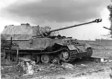
Early steering systems were inefficient and lost so much power that they were ineffective for heavy vehicles. Holt Manufacturing Company (the ancestor of Caterpillar Inc.) whose track design influenced early tanks, experimented with a petrol-electric transmission in their Holt gas electric tank. A comparable design was used on the French Saint-Chamond and in turn adapted to be fitted in one British Mark II heavy tank to compete against other transmission developments including a Mk II fitted with a British Westinghouse petrol-electric and the original prototype heavy tank "Mother" with a Daimler petrol-electric drive. The winner was a conventional design with epicyclic gearboxes.[8] None of these were particularly successful, although several hundred units of the Saint-Chamond were produced.[9]
While moderately successful, these early systems were large and extremely heavy; the one in the Saint-Chamond added five tons.[9][10] The other designs, and follow-ons using a similar system, were generally dismissed as impractical.[10]
Some of the first attempts at new electric transmissions were made by the British in the early-war period for the TOG1 heavy tank design (a petrol engine drove twin generators which powered one electric motor per track), and by the Germans as part of mid-war experiments in heavy tanks. The most notable among the German efforts was the VK 4501 (P), a design by Porsche for a heavy tank which lost out to Henschel.[11] The 100 or so chassis from this rejected design were converted to a self-propelled anti-tank gun, the Elefant (initially "Ferdinand") Panzerjäger.[12] This style of transmission was also used in the super-heavy Panzer VIII Maus. In practice, the powertrain of the Porsche designs proved even less reliable than the traditional type, and by the late war era the supply of copper was too limited to consider using so much in drivetrain motors.[13]
References
Citations
- Ogorkiewicz 2015, p. 298.
- Edwards 1988, p. 47.
- Ogorkiewicz 2015, p. 297.
- "Transmission for T-72 Tank and Its Versions". Kharkiv Morozov Machine Building.
- Edwards 1988, p. 48.
- Ogorkiewicz 2015, p. 300.
- Tetrarch Tank. The Tank Museum. 31 May 2019. Tank Chats #76.
- Fletcher, David (2004), British Mark I Tank 1916, New Vanguard 100, Osprey Publishing, p. 39
- Jackson, Robert (2010). 101 Great Tanks. Rosen Publishing. p. 9. ISBN 978-1-4358-3595-5.
- Smithers, A J (1986). A New Excalibur: The Development of the Tank 1909–1939. Pen and Sword. p. 92. ISBN 978-0-436-47520-7.
- Ogorkiewicz 2015, p. 130.
- Carruthers, Bob (2013). Handbook on German Military Forces. Pen and Sword. p. 409. ISBN 978-1-78159-215-1.
- Ogorkiewicz 2015, pp. 300–301.
Bibliography
- Edwards, Phillip (September 1988). "Tank Steering Systems (Differentials, the Theory and Practice)". Constructor Quarterly: 47–48.
- Fletcher, David (2016). British Battle Tanks: World War I to 1939. Bloomsbury Publishing. ISBN 978-1-4728-1756-3.
- Ogorkiewicz, Richard (2015). Tanks: 100 years of evolution. Bloomsbury Publishing. ISBN 978-1-4728-1305-3.
External links
- Tracked Vehicle Steering lists most of these systems along with diagrams.