MicroMegas detector
The MicroMegas detector (Micro-Mesh Gaseous Structure) is a gaseous particle detector coming from the development of the wire chamber. Invented in 1992[1] by Georges Charpak and Ioannis Giomataris, the Micromegas detectors are mainly used in experimental physics, in particular in particle physics, nuclear physics and astrophysics for the detection of ionising particles.
The Micromegas are light detectors in order to minimize the perturbation on the impinging particle. From their small amplification gap, they have fast signals in the order of 100 nanoseconds. They are a type of micropattern gaseous detector with a spatial resolution below one hundred micrometers.[2] Nowadays, the use of the Micromegas technology is growing throughout the different fields of experimental physics.
Working principle

A particle detector is used to detect a passing particle and obtain information such as its position, arrival time and momentum. In experimental physics, the particle is usually coming from a particle accelerator but it can also come from space (cosmic ray), from a nuclear reactor or a radioactive isotope.
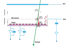
The Micromegas detector detects particles by amplifying the charges that have been created by ionisation in the gas volume. In a Micromegas detector, this gas volume is divided in two by a metallic micro-mesh (“Micromesh” on the schematic) placed between 25 μm and 150 μm of the readout electrode (Strips on the schematic). The micro-mesh is the key element since it allows, at the same time, a high gain of 104 and a fast signal of 100 ns.
Ionisation and charge amplification
While passing through the detector, a particle will ionise the gas atoms by pulling up an electron creating an electron/ion pair (1). When no electric field is applied, the ion/electron pair recombines and nothing happens. But here, within an electric field in the order of 400 V/cm the electron will drift (2) toward the amplification electrode (the mesh) and the ion toward the cathode. When the electron arrives close to the mesh (3), it enters an intense electric field (typically on the order of 40 kV/cm in the amplification gap). Accelerated by this field, the electron acquires enough energy to produce ion/electron pairs that will also ionise the gas, creating pairs; this is the avalanche effect (4). By this means, several thousand pairs are created from hundreds of primary charges, which originate from the interactions with the impinging particle. The primary charges need to be multiplied to create a significant signal. and lastly, we read the electronic signal on the readout electrode (5) by a charge amplifier. The readout electrode is usually segmented in strips and/or pixels in order to obtain the position of the impinging particle in the detector. The amplitude and the shape of the signal, read via the electronic on the readout electrode, gives information on the time and energy of the particle.
Analog signal of a Micromegas

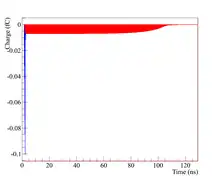
The signal is induced by the movement of charges between the micro-mesh and the readout electrode (this volume is called the amplification gap). The 100 nanosecond signal consists of an electron peak (blue) and an ion tail (red). Since the electron mobility in gas is over 1000 times higher than the ion mobility, the electronic signal is much shorter (below 3ns) than the ionic one. That is why it is used to precisely measure the time. The ionic signal carries more than half of the signal and is used to reconstruct the energy of the particle.
History
First concept at the Hadron Blind Detector
In 1991, to improve the detection of hadrons at the Hadron Blind Detector experiment,[3] I. Giomataris and G. Charpak reduced the amplification gap of a parallel plate detector (a type of spark chamber) in order to speed up the signal. A 1 mm amplification gap prototype was built for the HDB experiment but the gain was not uniform enough to be used in the experiment. The millimetre gap was not controlled enough and created large gain fluctuations. Nevertheless, the benefits of a reduce amplification gap had been demonstrated and the micro-mesh gaseous structure or Micromegas concept was born in October 1992, shortly before the announcement of the Nobel prize attribution to Georges Charpak for the invention of the wire chambers. Georges Charpak used to say that this detector and some other new concepts belonging to the family of micro-pattern gaseous detectors (MPGDs) will revolutionise nuclear and particle physics just as his detector did.[4]
The Micromegas technology research and development
Starting in 1992 at CEA Saclay and CERN, the Micromegas technology has been developed to provide more stable, reliable, precise and faster detectors. In 2001, twelve large Micromegas detectors of 40 x 40 cm2 were used for the first time in a large scale experiment at COMPASS situated on the Super Proton Synchrotron accelerator at CERN. Since 2002 they have been detecting millions of different particles per seconds and still continue today.
Another example of the development of the Micromegas detectors is the invention of the “bulk” technology. The “bulk” technology consists of the integration of the micro-mesh with the printed circuit board (that carries the readout electrodes) in order to build a monolithic detector. Such a detector is very robust and can be produced via an industrial process (a successful implementation was demonstrated by 3M in 2006[5]) allowing public applications. For instance, by modifying the micro-mesh in order to make it photo-sensitive to UV light, the Micromegas can be used to detect forest fires.[6] A photo-sensitive Micromegas is also used for fast-timing applications. The PICOSEC-Micromegas uses a Cherenkov radiator and a photocathode in front of the gaseous volume and a time resolution of 24 ps is measured with minimum ionizing particles (MIP).[7]

Micromegas detectors in experimental physics
The Micromegas detectors are now used in several experiments :
- Hadronic physics: COMPASS, NA48, and projects for the ILC-TPC and CLAS12 at J-lab are under active study
- Particle physics: T2K, CAST, HELAZ, IAXO
- Neutron physics : nTOF, ESS nBLM[8]
Micromegas detector will be used in the ATLAS experiment, as part of their upgrade of its future muon spectrometer.[9]
Notes and references
- Giomataris, Y.; Rebourgeard, Ph.; Robert, J.P.; Charpak, G. (1996). "MICROMEGAS: a high-granularity position-sensitive gaseous detector for high particle-flux environments". Nuclear Instruments and Methods in Physics Research Section A: Accelerators, Spectrometers, Detectors and Associated Equipment. 376 (1): 29–35. Bibcode:1996NIMPA.376...29G. doi:10.1016/0168-9002(96)00175-1.
- J.P. Cussonneau et al./Nucl. Instr. and Meth. in Phys. Res. A 419 (1998) 452—459
- Hadron Blind Detector(HBD): created by : ref: I. Giomataris,G. Charpak, NIM A310(1991)589
- "Georges Charpak – a true man of science – CERN Courier". 30 November 2010.
- "Micro Patterned Gas Detector Development Group at Purdue University". Archived from the original on 2011-09-27. Retrieved 2011-06-13.
- "FORFIRE : Micromegas in the fight against forest fires". Retrieved October 5, 2020.
- Bortfeldt, J.; et al. (2018). "PICOSEC: Charged particle timing at sub-25 picosecond precision with a Micromegas based detector". Nuclear Instruments and Methods in Physics Research. A903: 317–325. arXiv:1712.05256. Bibcode:2018NIMPA.903..317B. doi:10.1016/j.nima.2018.04.033.
- Papaevangelou, Thomas; et al. (2018). "ESS nBLM: Beam Loss Monitors based on Fast Neutron Detection". Proceedings of the 61st ICFA Advanced Beam Dynamics Workshop on High-Intensity and High-Brightness Hadron Beams. HB2018. doi:10.18429/JACoW-HB2018-THA1WE04.
- the ATLAS Collaboration (2013). New Small Wheel Technical Design Report. Technical Design Report ATLAS.