Yaw system
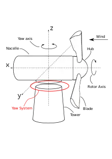
The yaw system of wind turbines is the component responsible for the orientation of the wind turbine rotor towards the wind.

History
The task of orienting the rotor into the wind was a complicated issue already for historical windmills. The first windmills able to rotate in order to "face" the wind appeared in the mid-18th century.[1] Their rotatable nacelles were mounted on the main structure of the windmill using primitive wooden gliding bearings lubricated with animal fat. The necessary yawing torque was created by means of animal power, human power or even wind power (implementation of an auxiliary rotor known as fantail).
Vertical-axis wind turbines (VAWTs) do not need a yaw system since their vertical rotors can face the wind from any direction and only their self rotation gives the blades a clear direction of the air flow.[1] Horizontal-axis wind turbines (HAWTs), however, need to orient their rotors into and out of the wind and they achieve that by means of passive or active yaw systems.
HAWTs employ some sort of yaw system which can be passive or active. Both passive and active systems have advantages and disadvantages and various design solutions (both active and passive) are being tried in order to find the optimal design for each wind turbine depending on its size, cost and purpose of operation.
Types

Active yaw systems
The active yaw systems are equipped with some sort of torque producing device able to rotate the nacelle of the wind turbine against the stationary tower based on automatic signals from wind direction sensors or manual actuation (control system override). The active yaw systems are considered to be the state of the art for all the modern medium and large sized wind turbines, with a few exceptions proving the rule (e.g. Vergnet). The various components of the modern active yaw systems vary depending on the design characteristics but all the active yaw systems include a means of rotatable connection between nacelle and tower (yaw bearing), a means of active variation of the rotor orientation (i.e. yaw drive), a means of restricting the rotation of the nacelle (yaw brake) and a control system which processes the signals from wind direction sensors (e.g. wind vanes) and gives the proper commands to the actuating mechanisms.
The most common types of active yaw systems are:
- Roller yaw bearing - Electric yaw drive - Brake: The nacelle is mounted on a roller bearing and the azimuth rotation is achieved via a plurality of powerful electric drives. A hydraulic or electric brake fixes the position of the nacelle when the re-orientation is completed in order to avoid wear and high fatigue loads on wind turbine components due to backlash. Systems of this kind are used by most of the wind turbine manufacturers and are considered to be reliable and effective but also quite bulky and expensive.
- Roller yaw bearing - Hydraulic yaw drive: The nacelle is mounted on a roller bearing and the azimuth rotation is achieved via a plurality of powerful hydraulic motors or ratcheting hydraulic cylinders. The benefit of the yaw system with hydraulic drives has to do with the inherent benefits of the hydraulic systems such as the high power-to-weight ratio and high reliability. On the downside however the hydraulic systems are always troubled by leakages of hydraulic fluid and clogging of their high pressure hydraulic valves. The hydraulic yaw systems often (depending on the system design) also allow for the elimination of the yaw brake mechanism and their replacement with cut-off valves.
- Gliding yaw bearing - Electric yaw drive: The nacelle is mounted on a friction based gliding bearing and the azimuth rotation is achieved via a plurality of powerful electric drives. The need for a yaw brake is eliminated and depending on the size of the yaw system (i.e. size of the wind turbine) the gliding bearing concept can lead to significant cost savings.
- Gliding yaw bearing - Hydraulic yaw drive: The nacelle is mounted on a friction based gliding bearing and the azimuth rotation is achieved via a plurality of powerful hydraulic motors or ratcheting hydraulic cylinders. This system combines the characteristics of the aforementioned gliding bearing and hydraulic motor systems.
Passive yaw systems
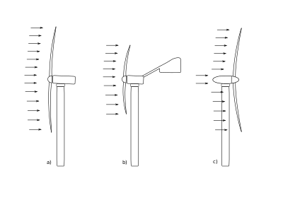
The passive yaw systems utilize the wind force in order to adjust the orientation of the wind turbine rotor into the wind. In their simplest form these system comprise a simple roller bearing connection between the tower and the nacelle and a tail fin mounted on the nacelle and designed in such a way that it turns the wind turbine rotor into the wind by exerting a "corrective" torque to the nacelle. Therefore, the power of the wind is responsible for the rotor rotation and the nacelle orientation. Alternatively in case of downwind turbines the tail fin is not necessary since the rotor itself is able to yaw the nacelle into the wind. In the event of skew winds the "wind pressure" on the swept area causes a yawing moment around the tower axis (z-axis) which orients the rotor.[1]
The tail fin (or wind vane) is commonly used for small wind turbines since it offers a low cost and reliable solution. It is however unable to cope with the high moments required to yaw the nacelle of a large wind turbine. The self-orientation of the downwind turbine rotors however is a concept able to function even for larger wind turbines. The French wind turbine manufacturer Vergnet has several medium and large self-orienting downwind wind turbines in production.
Passive yaw systems have to be designed in a way that the nacelle does not follow the sudden changes in wind direction with too fast a yaw movement, in order to avoid high gyroscopic loads. Additionally the passive yaw systems with low yaw-friction are subjected to strong dynamic loads due to the periodic low amplitude yawing caused by the variation of the inertia moment during the rotor rotation. This effect becomes more severe with the reduction of the number of blades.
The most common passive yaw systems are:
- Roller Bearing (free system): The nacelle is mounted on a roller bearing and it is free to rotate towards any direction. The necessary moment comes from a tail fin or the rotor (downwind wind turbines)
- Roller Bearing - Brake (Semi-active system): The nacelle is mounted on a roller bearing and it is free to rotate towards any direction, but when the necessary orientation is achieved an active yaw brake arrests the nacelle. This prevents the uncontrolled vibration and reduced gyroscopic and fatigue loads.
- Gliding Bearing/Brake (Passive system): The nacelle is mounted on a gliding bearing and it is free to rotate towards any direction. The inherent friction of the gliding bearing achieves a quasi-active way of operation.
Components

Yaw bearing
One of the main components of the yaw system is the yaw bearing. It can be of the roller or gliding type and it serves as a rotatable connection between the tower and the nacelle of the wind turbine. The yaw bearing should be able to handle very high loads, which apart from the weight of the nacelle and rotor (the weight of which is in the range of several tenths of tons) include also the bending moments caused by the rotor during the extraction of the kinetic energy of the wind.
Yaw drives
The yaw drives exist only on the active yaw systems and are the means of active rotation of the wind turbine nacelle. Each yaw drive consists of powerful electric motor (usually AC) with its electric drive and a large gearbox, which increases the torque. The maximum static torque of the biggest yaw drives is in the range of 200.000Nm with gearbox reduction ratios in the range of 2000:1.[2] Consequently, the yawing of the large modern turbines is relatively slow with a 360° turn lasting several minutes.
Yaw brake

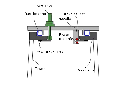
In order to stabilize the yaw bearing against rotation a means of braking is necessary. One of the simplest ways to realize that task is to apply a constant small counter-torque at the yaw drives in order to eliminate the backlash between gear-rim and yaw drive pinions and to prevent the nacelle from oscillating due to the rotor rotation. This operation however greatly reduces the reliability of the electric yaw drives, therefore the most common solution is the implementation of a hydraulically actuated disk brake.
The disk brake requires a flat circular brake disk and plurality of brake calipers with hydraulic pistons and brake pads . The hydraulic yaw brakes are able to fix the nacelle in position thus relieving the yaw drives from that task. The cost however of the yaw brake in combination with the requirement of a hydraulic installation (pump, valves, pistons) and its installation in the vicinity of brake pads sensitive to lubricant contamination is often an issue.
A compromise that offers several advantages is the use of electric yaw brakes. These replace the hydraulic mechanism of the conventional brakes and with electro-mechanically actuated brake calipers. The use of electric yaw brakes eliminates the complexity of the hydraulic leakages and the subsequent problems that these cause to the yaw brake operation.[3]
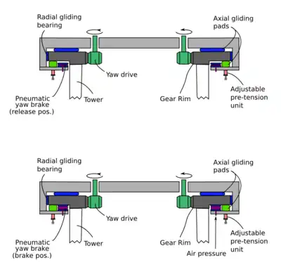
Several wind turbine design and manufacturing companies experiment with alternative yaw breaking methods in order to eliminate the drawbacks of the existing systems and to reduce the cost of the system. One of these alternatives involves the use of air pressure in order to achieve the necessary yaw braking moment. In this case, some of the gliding surface (usually the axial, due to higher available surface) is utilized in order to accommodate the yaw brake pads and the pneumatic brake mechanism. The pneumatic actuator can be a conventional pneumatic cylinder or even a flexible air chamber which inflates when supplied with pressurized air. Such a device is able to exert very high braking forces due to the high active surface. This is achieved with a simple industrial air pressure compression system (6–10 bar or 600–1,000 kPa or 87–145 psi) which is a reliable and low cost solution. Furthermore, in the event of leakage, the environmental impact is practically zero compared to hydraulic oil leakages. Finally, brake actuators can be produced at very low cost from lightweight plastic materials thus significantly reducing the overall cost of the system.
Yaw vane (passive systems)
The yaw vane (or tail fin) is a component of the yaw system used only on small wind turbines with passive yaw mechanisms. It is nothing more than a flat surface mounted on the nacelle by means of a long beam. The combination of the large surface area of the fin and the increased length of the beam create a considerable torque which is able to rotate the nacelle despite the stabilizing gyroscopic effects of the rotor. The required surface area however for a tail fin to be able to yaw a large wind turbine is enormous thus rendering the use of such a device un-economical.
References
- Wind Power Plants, R. Gasch and J. Twele, Solarpraxis, ISBN 3-934595-23-5
- Bonfiglioli Power & Control Solutions
- Hanning & Kahl GmbH Azimutbremsen
Further reading
- Wind Power Plants, R. Gasch and J. Twele, Solarpraxis, ISBN 3-934595-23-5
- Wind Energy Handbook, T. Burton [et al.], John Wiley & Sons, Ltd, ISBN 0-471-48997-2
- How to build a wind turbine - The axial flux windmill plans, H. Piggott Scoraigwind