VESA Plug and Display
VESA Plug and Display (abbreviated as P&D) is a video connector that carries digital signals for monitors, such as flat panel displays and video projectors, ratified by Video Electronics Standards Association (VESA) in 1997. Introduced around the same time as the competing connectors for the Digital Visual Interface (DVI, 1999) and VESA's own Digital Flat Panel (DFP, 1999), it was marketed as a replacement for the VESA Enhanced Video Connector (EVC, 1994). Unlike DVI, it never achieved widespread implementation.

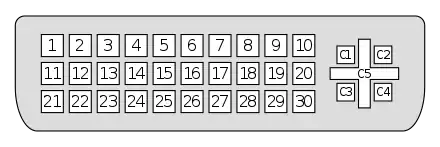
The P&D connector shares the 30-pin plus quad-coax layout of EVC, which carries digital video, analog video, and data over Universal Serial Bus (USB) and IEEE 1394 (FireWire). At a minimum, the P&D connector is required to carry digital video, in which case the connector is designated P&D-D; when both digital and analog video are included, the connector is designated P&D-A/D.
Design
| Mark | Meaning | Mark | Meaning | |
|---|---|---|---|---|
| A1 | RS-170 | D | Non-standard | |
| A2 | RS-343 | D1 | 25–65 MHz | |
| A3 | Euro | D2 | 65–112 MHz | |
| A4 | VESA | D3 | 112–160 MHz | |
| IEEE | Supports IEEE 1394-1995 | USB | Supports USB | |
| (none) | No IEEE 1394 support | (none) | No USB support | |
The P&D receptacle and plug are required to bear a standardized symbol to designate the standards with which it is compatible. The upper left quadrant designates analog video support. The upper right quadrant designates digital video support. The lower quadrants designate IEEE 1394 and USB support.[1]: §9.4
All P&D connectors are required to carry single-link TMDS digital video signal (max 160 MHz), and support VESA Display Data Channel version 2 at a minimum.[1]: §10.1 Maximum resolution is 1600×1280 with a 60 Hz refresh rate.[1]: §1.2.2
Analogue video signals, if supported, must be provided as three separate color channels (red / green / blue) along with one composite or two (horizontal & vertical) sync signals.[1]: §9 The nominal impedance of each signal line is 75 Ω and each channel must be capable of carrying a bandwidth of at least 2.4 GHz.[1]: §7.10.1.9 The type designation for the analogue video signals designates the voltage values of the signals only, including the Type 4 (VESA) analog DC protocol introduced with EVC:[1]: §4.5.2.1
| Signal | Type 1 RS-170 | Type 2 RS-343 | Type 3 Euro | Type 4 VESA |
|---|---|---|---|---|
| Peak | +1.000 V | +0.714 V | +0.700 V | +0.700 VDC |
| Minimum | +0.075 V | +0.054 V | +0.000 V | +0.000 VDC |
| Blank | Reference | Reference | Reference | +0.000 VDC |
| Sync. tip | -0.400 V | -0.286 V | -0.300 V | None |
The P&D connector supports optional charging power at 18–20 VDC and up to 1.5 A.[1]: §4.6 In addition, a stereoscopic display synchronization signal is supported as an option.[1]: §4.7 Data signals over USB and FireWire also are optional.
USB version is not specified,[1]: §8.5 but if supported, it would have been intended for contemporary USB standards. The USB connector is intended for passing mouse movements from a projector's wireless remote to the computer's presentation software and for firmware upgrades.[2]
FireWire, if supported, must be compliant to IEEE 1394-1995 specification.[1]: §8.6
Connectors
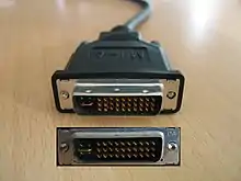
Although the pin layout is copied from VESA EVC, the connector shell is slightly different: EVC uses a trapezoid shape, while P&D uses a D-shape. The interface is protected by patents issued to Molex.[1]: §7.1 With the introduction of P&D, EVC continued as the connector for analog-only signals and is sometimes known as P&D-A; the EVC/P&D family was completed with combination analog/digital (P&D-A/D) and digital-only (P&D-D) connectors.[1]: §12.1 P&D-A/D is compatible with EVC devices (except for the missing VESA EVC features), P&D-D is not.
Host (receptacle) Monitor (plug) |
EVC[lower-alpha 1] | P&D-A/D | P&D-D |
|---|---|---|---|
| EVC[lower-alpha 1] | |||
| P&D-D |
- Notes
- For this table, it is assumed EVC is the analog-only implementation
In addition to the regular P&D connector, the standard also specifies a 40-pin microribbon connector, which is only defined when making digital video connection via P&D-D.[1]: §10.3
The P&D port is sometimes mistaken as an alternative form of the Apple Display Connector,[3] but ADC carries higher current, has different pin layout, and does not support FireWire.
| Pin | Function | P&D-A/D | P&D-D |
|---|---|---|---|
| 1 | General purpose, third make | TMDS Data2 + | |
| 2 | TMDS Data2 - | ||
| 3 | TMDS Data2 return | ||
| 4 | Horizontal & Vertical sync return | Not used | |
| 5 | Horizontal sync / Composite sync | Not used | |
| 6 | Vertical sync | Not used | |
| 7 | TMDS Clock return | ||
| 8 | General purpose, fourth make | Charge power + | |
| 9 | General purpose, third make | 1394 pair A, data - | |
| 10 | 1394 pair A, data + | ||
| 11 | TMDS Data1 + | ||
| 12 | TMDS Data1 - | ||
| 13 | TMDS Data1 return | ||
| 14 | TMDS Clock + | ||
| 15 | TMDS Clock - | ||
| 16 | USB data + | ||
| 17 | USB data - | ||
| 18 | General purpose, fourth make | 1394 outer shield (optional) & Charge Power return | |
| 19 | General purpose, third make | 1394 Vg | |
| 20 | 1394 Vp | ||
| 21 | TMDS Data0 + | ||
| 22 | TMDS Data0 - | ||
| 23 | TMDS Data0 return | ||
| 24 | Stereo sync | Not used | |
| 25 | DDC return & Stereo sync return | ||
| 26 | DDC data (SDA) | ||
| 27 | DDC clock (SCL) | ||
| 28 | General purpose, fourth make | +5 VDC | |
| 29 | General purpose, third make | 1394 pair B, Clock + | |
| 30 | 1394 pair B, Clock - | ||
| C1 | Quasi-Coaxial, fourth make | Red Video Out | Not used |
| C2 | Green Video Out | Not used | |
| C3 | Pixel clock (optional) | Not used | |
| C4 | Blue Video Out | Not used | |
| C5 | Common ground for quasi-coaxial lines, second make | Video / Pixel Clock Return | Used as mechanical key |
Alternative names
- M1-DA, a name used by InFocus (often shortened to M1)
References
- "VESA Plug and Display (P&D) Standard, Version 1" (PDF). Video Electronics Standards Association. June 11, 1997. Archived from the original (PDF) on July 4, 2003.
- "M1 to DVI-D/USB cable $59.00*(US)". InFocus. Archived from the original on February 4, 2012.
- "What the hell is… Apple's Display Connector?".

