Sliding criterion (geotechnical engineering)
The sliding criterion (discontinuity) is a tool to estimate easily the shear strength properties of a discontinuity in a rock mass based on visual and tactile (i.e. by feeling) characterization of the discontinuity.[1][2][3][4] The shear strength of a discontinuity is important in, for example, tunnel, foundation, or slope engineering, but also stability of natural slopes is often governed by the shear strength along discontinuities.
The sliding-angle is based on the ease with which a block of rock material can move over a discontinuity and hence is comparable to the tilt-angle as determined with the tilt test, but on a larger scale. The sliding criterion has been developed for stresses that would occur in slopes between 2 and 25 metres (6.6 and 82.0 ft), hence, in the order of maximum 0.6 megapascals (87 psi). The sliding criterion is based on back analyses of slope instability and earlier work of ISRM[5] and Laubscher.[6] The sliding criterion is part of the Slope Stability Probability Classification (SSPC)[3] system for slope stability analyses.
| characterization | factor | ||
|---|---|---|---|
| Roughness large scale (Rl) | wavy | 1.00 | |
| slightly wavy | 0.95 | ||
| curved | 0.85 | ||
| slightly curved | 0.80 | ||
| straight | 0.75 | ||
| Roughness small scale (Rs) | rough stepped/irregular | 0.95 | |
| smooth stepped | 0.90 | ||
| polished stepped | 0.85 | ||
| rough undulating | 0.80 | ||
| smooth undulating | 0.75 | ||
| polished undulating | 0.70 | ||
| rough planar | 0.65 | ||
| smooth planar | 0.60 | ||
| polished planar | 0.55 | ||
| Infill material (Im) | cemented/cemented infill | 1.07 | |
| no infill - surface staining only | 1.00 | ||
| non-softening & sheared material, e.g. free of clay, talc | coarse | 0.95 | |
| medium | 0.90 | ||
| fine | 0.85 | ||
| softening & soft-sheared material, e.g. clay, talc | coarse | 0.75 | |
| medium | 0.65 | ||
| fine | 0.55 | ||
| gouge < irregularities | 0.42 | ||
| gouge > irregularities | 0.17 | ||
| flowing material | 0.05 | ||
| Karst (Ka) | none | 1.00 | |
| karst | 0.92 | ||
Sliding-angle
The sliding-angle is calculated as follows:
- where sliding-angle is in degrees, and
- Rl = roughness large scale
- Rs = roughness small scale
- Im = infill material in the discontinuity
- Ka = karst; presence of karst (solution) features along the discontinuity
(The values for the parameters are listed in table 1 and explained below)

Roughness large scale (Rl)
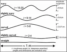
The roughness large scale (Rl) is based on visual comparison of the trace (with a length of about 1 m) or surface (with an area of about 1 x 1 m2 of a discontinuity with the example graphs in figure 1. This results in a descriptive term: wavy, slightly wavy, curved, slightly curved, or straight. The corresponding factor for Rl is listed in table 1.
The roughness large scale (Rl) contributes only to the friction along the discontinuity when the walls on both sides of the discontinuity are fitting, i.e. the asperities on both discontinuity walls match. If the discontinuity is non-fitting, the factor Rl = 0.75.

Roughness small scale (Rs)
The roughness small scale (Rs) is established visually and tactile (by feeling).
The first term rough, smooth, or polished is established by feeling the surface of the discontinuity; rough hurts when fingers are moved over the surface with some (little) force, smooth feels that there is resistance to the fingers, while polished gives a feeling about similar to the surface of glass.
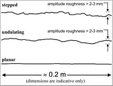
The second term is established visually. The trace (with a length of about 0.2 m) or surface (with an area of about 0.2 x 0.2 m2 of a discontinuity is compared with the example graphs in figure 2; this gives stepped, undulating, or planar. The two terms of visual and tactile give a combined term and the corresponding factor is listed in table 1.
The visual part of the roughness small scale (Rs) contributes only to the friction along the discontinuity if the walls on both sides of the discontinuity are fitting, i.e. the asperities on both discontinuity walls match. If the discontinuity is non-fitting, the visual part of the roughness small scale (Rs) should be taken as planar for the calculation of the sliding-angle, and hence, the roughness small scale (Rs) can be only rough planar, smooth planar, or polished planar.
Infill in discontinuity (Im)
Infill material in a discontinuity has often a marked influence on the shear characteristics. The different options for infill material are listed in table 1, and below follows a short explanation for each option.
Cemented discontinuity or cemented infill
A cemented discontinuity or a discontinuity with cemented infill has higher shear strength than a non-cemented discontinuity if the cement or cemented infill is bonded to both discontinuity walls. Note that cement and cement bounds that are stronger than the surrounding intact rock ceases the discontinuity to be a mechanical plane of weakness, meaning the 'sliding-angle' has no validity.
No infill
No infill describes a discontinuity that may have coated walls but no other infill.
Non-softening infill
Non-softening infill material is material that does not change in shear characteristics under the influence of water nor under the influence of shear displacement. The material may break but no greasing effect will occur. The material particles can roll but this is considered to be of minor influence because, after small displacements, the material particles generally will still be very angular. This is further sub-divided in coarse, medium, and fine for the size of the grains in the infill material or the size of the grains or minerals in the discontinuity wall. The larger of the two should be used for the description. The thickness of the infill can be very thin, sometimes not more than a dust coating.
Softening infill
Softening infill material will under the influence of water or displacements, attain in lower shear strength and will act as a lubricating agent. This is further sub-divided in coarse, medium, and fine for the size of the grains in the infill material or the size of the grains or minerals in the discontinuity wall. The larger of the two should be used for the description. The thickness of the infill can be very thin, sometimes not more than a dust coating.
Gouge infill
Gouge infill means a relatively thick and continuous layer of infill material, mainly consisting of clay but may contain rock fragments. The clay material surrounds the rock fragments in the clay completely or partly, so that these are not in contact with both discontinuity walls. A sub-division is made between less thick and thicker than the amplitude of the roughness of the discontinuity walls. If the thickness is less than the amplitude of the roughness, the shear strength will be influenced by the wall material and the discontinuity walls will be in contact after a certain displacement. If the infill is thicker than the amplitude, the friction of the discontinuity is fully governed by the infill.
Flowing material infill
Very weak and not compacted infill in discontinuities flows out of the discontinuities under its own weight or as a consequence of a very small trigger force (such as water pressure, vibrations due to traffic or the excavation process, etc.).
Karst (Ka)
The presence of solution (karst) features along the discontinuity.
See also
References
- Hack, H.R.G.K.; Price, D.G. (September 25–29, 1995). Fujii, T. (ed.). Determination of discontinuity friction by rock mass classification (PDF). Proceedings 8th International Society for Rock Mechanics (ISRM) congress. Vol. 3. Tokyo, Japan: Balkema, Rotterdam, Taylor & Francis. pp. 23–27. ISBN 978-90-5410-576-3.
- Hack, R. (1998) [1st edition; 2nd edition 1998]. Slope Stability Probability Classification (SSPC) (PDF). ITC publication 43. Technical University Delft & Twente University - International Institute for Aerospace Survey and Earth Sciences (ITC Enschede), Netherlands. p. 258. ISBN 978-90-6164-154-4.
- Hack, R.; Price, D.; Rengers, N. (2003). "A new approach to rock slope stability – a probability classification (SSPC)". Bulletin of Engineering Geology and the Environment. 62 (2): 167–184. doi:10.1007/s10064-002-0155-4.
- Price, D.G. (2008). De Freitas, M.H. (ed.). Engineering Geology: Principles and Practice. Springer. p. 450. ISBN 978-3-540-29249-4.
- ISRM (2007). Ulusay, R.; Hudson, J.A. (eds.). The Blue Book - The Complete ISRM Suggested Methods for Rock Characterization, Testing and Monitoring: 1974-2006. Ankara: ISRM & ISRM Turkish National Group. p. 628. ISBN 978-975-93675-4-1.
- Laubscher, D.H. (1990). "A geomechanics classification system for rating of rock mass in mine design". Journal South African Institute of Mining and Metallurgy. 90 (10): 257–273. ISSN 0038-223X.
Further reading
- Andrade, P.S.; Saraiva, A.A. (2008). "Estimating the joint roughness coefficient of discontinuities found in metamorphic rocks". Bulletin of Engineering Geology and the Environment. 67 (3): 425–434. doi:10.1007/s10064-008-0151-4. hdl:10316/7611.
- Filipello, A.; Giuliani, A.; Mandrone, G. (2010). "Rock Slopes Failure Susceptibility Analysis: From Remote Sensing Measurements to Geographic Information System Raster Modules". American Journal of Environmental Sciences. 6 (6): 489–494. doi:10.3844/ajessp.2010.489.494.
- A.J., Geertsema (2003). The shear strength of rock joints with special reference to dam foundations; PhD Dissertation. Faculty of Natural and Agricultural Sciences, School of Physical Sciences, Department of Geology, University of Pretoria, South Africa. urn: etd-09252008-170958.
- Huisman, M.; Hack, H.R.G.K.; Nieuwenhuis, J.D. (2004). Schubert, W. (ed.). Observed rock mass degradation and resulting slope instability. Rock Engineering – Theory and Practice. EUROCK 2004 & 53rd Geomechanics Colloquium. Salzburg, Austria: Verlag Glückauf, Essen, Germany. pp. 449–452. ISBN 3-7739-5995-8.