Air brake (aeronautics)
In aeronautics, air brakes or speed brakes are a type of flight control surface used on an aircraft to increase the drag on the aircraft.[1] Air brakes differ from spoilers in that air brakes are designed to increase drag while making little change to lift, whereas spoilers reduce the lift-to-drag ratio and require a higher angle of attack to maintain lift, resulting in a higher stall speed.[2]


Introduction
An air brake is a part of an aircraft. When extended into the airstream, it causes an increase in the drag on the aircraft. When not in use, it conforms to the local streamlined profile of the aircraft in order to help minimise the drag.[3]
History
In the early decades of powered flight, air brakes were flaps mounted on the wings. They were manually controlled by a lever in the cockpit, and mechanical linkages to the air brake.
An early type of air brake, developed in 1931, was fitted to the aircraft wing support struts.[4]
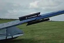
In 1936, Hans Jacobs, who headed Nazi Germany's Deutsche Forschungsanstalt für Segelflug (DFS) glider research organization before World War II, developed blade-style self-operating dive brakes, on the upper and lower surface of each wing, for gliders.[5] Most early gliders were equipped with spoilers on the wings in order to adjust their angle of descent during approach to landing. More modern gliders use air brakes which may spoil lift as well as increase drag, dependent on where they are positioned.
A British report[6] written in 1942 discusses the need for dive brakes to enable dive bombers, torpedo bombers and fighter aircraft to meet their respective combat performance requirements and, more generally, glide-path control. It discusses different types of air brakes and their requirements, in particular that they should have no appreciable effect on lift or trim and how this may be achieved with split trailing edge flaps on the wings, for example. There was also a requirement to vent the brake surfaces using numerous perforations or slots to reduce airframe buffeting.
A US report[7] written in 1949 describes numerous air brake configurations, and their performance, on wings and fuselage for propeller and jet aircraft.
Air brake configurations
Often, characteristics of both spoilers and air brakes are desirable and are combined - most modern airliner jets feature combined spoiler and air brake controls. On landing, the deployment of these spoilers ("lift dumpers") causes a significant reduction in wing lift, so the weight of the aircraft is transferred from the wings to the undercarriage. The increased weight increases the available friction force for braking. In addition, the form drag created by the spoilers directly assists the braking effect. Reverse thrust is also used to help slow the aircraft after landing.[8]
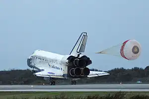
Virtually all jet-powered aircraft have an air brake or, in the case of most airliners, lift spoilers that also act as air brakes. Propeller-driven aircraft benefit from the natural braking effect of the propeller when engine power is reduced to idle, but jet engines have no similar braking effect, so jet-powered aircraft must use air brakes to control speed and descent angle during landing approach. Many early jets used parachutes as air brakes on approach (Arado Ar 234, Boeing B-47) or after landing (English Electric Lightning).
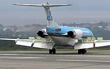
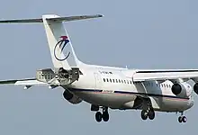
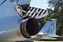
Split-tailcone air brakes have been used on the Blackburn Buccaneer naval strike aircraft designed in the 1950s and Fokker F28 Fellowship and British Aerospace 146 airliners. The Buccaneer air brake, when opened, reduced the length of the aircraft in the confined space on an aircraft carrier.
The F-15 Eagle, Sukhoi Su-27, F-18 Hornet and other fighters have an air brake located just behind the cockpit.
Split control surfaces
The deceleron is an aileron that functions normally in flight but can split in half such that the top half goes up as the bottom half goes down to brake. This technique was first used on the F-89 Scorpion and has since been used by Northrop on several aircraft, including the B-2 Spirit.
The Space Shuttle used a similar system. The vertically-split rudder opened in "clamshell" fashion on landing to act as a speed brake.[9]
References
- Wragg, David W. (1973). A Dictionary of Aviation (first ed.). Osprey. p. 13. ISBN 9780850451634.
- "Speed brake". Britannica. Retrieved 28 December 2019.
- Aircraft Design, Kundu 2010, ISBN 978 0 521 88516 4, p.283
- "Air Brakes for Planes Greatly Reduce the Landing Speed". Popular Science. Vol. 122, no. 1. January 1933. p. 18.
- Reitsch, Hanna (April 1997) [1955]. The Sky My Kingdom: Memoirs of the Famous German WWII Test-Pilot (Greenhill Military Paperback). Stackpole Books. p. 108. ISBN 9781853672620.
- Davies, H.; Kirk, F. N. (June 1942). "A Résumé of Aerodynamic Data on Air Brakes" (PDF) (Technical Report). Ministry of Supply.
- Stephenson, Jack D. (September 1949). "The Effects of Aerodynamic Brakes Upon the Speed Characteristics of Airplanes" (PDF) (Technical Note). NACA.
- "Spoilers And Speedbrakes - SKYbrary Aviation Safety". www.skybrary.aero. Retrieved 2019-12-28.
- "Extract from NSTS Shuttle Reference Manual (1988): Space Shuttle Coordinate System – Vertical Tail". NASA. Archived from the original on 7 December 2021. Retrieved 25 October 2012.
External links
![]() Media related to Air brakes (aircraft) at Wikimedia Commons
Media related to Air brakes (aircraft) at Wikimedia Commons
