Structural engineering theory
Structural engineering depends upon a detailed knowledge of loads, physics and materials to understand and predict how structures support and resist self-weight and imposed loads. To apply the knowledge successfully structural engineers will need a detailed knowledge of mathematics and of relevant empirical and theoretical design codes. They will also need to know about the corrosion resistance of the materials and structures, especially when those structures are exposed to the external environment.
The criteria which govern the design of a structure are either serviceability (criteria which define whether the structure is able to adequately fulfill its function) or strength (criteria which define whether a structure is able to safely support and resist its design loads). A structural engineer designs a structure to have sufficient strength and stiffness to meet these criteria.
Loads imposed on structures are supported by means of forces transmitted through structural elements. These forces can manifest themselves as tension (axial force), compression (axial force), shear, and bending, or flexure (a bending moment is a force multiplied by a distance, or lever arm, hence producing a turning effect or torque).
Strength
Strength depends upon material properties. The strength of a material depends on its capacity to withstand axial stress, shear stress, bending, and torsion. The strength of a material is measured in force per unit area (newtons per square millimetre or N/mm², or the equivalent megapascals or MPa in the SI system and often pounds per square inch psi in the United States Customary Units system).
A structure fails the strength criterion when the stress (force divided by area of material) induced by the loading is greater than the capacity of the structural material to resist the load without breaking, or when the strain (percentage extension) is so great that the element no longer fulfills its function (yield).
See also:
Stiffness
Stiffness depends upon material properties and geometry. The stiffness of a structural element of a given material is the product of the material's Young's modulus and the element's second moment of area. Stiffness is measured in force per unit length (newtons per millimetre or N/mm), and is equivalent to the 'force constant' in Hooke's Law.
The deflection of a structure under loading is dependent on its stiffness. The dynamic response of a structure to dynamic loads (the natural frequency of a structure) is also dependent on its stiffness.
In a structure made up of multiple structural elements where the surface distributing the forces to the elements is rigid, the elements will carry loads in proportion to their relative stiffness - the stiffer an element, the more load it will attract. This means that load/stiffness ratio, which is deflection, remains same in two connected (jointed) elements. In a structure where the surface distributing the forces to the elements is flexible (like a wood-framed structure), the elements will carry loads in proportion to their relative tributary areas.
A structure is considered to fail the chosen serviceability criteria if it is insufficiently stiff to have acceptably small deflection or dynamic response under loading.
The inverse of stiffness is flexibility.
Safety factors
The safe design of structures requires a design approach which takes account of the statistical likelihood of the failure of the structure. Structural design codes are based upon the assumption that both the loads and the material strengths vary with a normal distribution.
The job of the structural engineer is to ensure that the chance of overlap between the distribution of loads on a structure and the distribution of material strength of a structure is acceptably small (it is impossible to reduce that chance to zero).
It is normal to apply a partial safety factor to the loads and to the material strengths, to design using 95th percentiles (two standard deviations from the mean). The safety factor applied to the load will typically ensure that in 95% of times the actual load will be smaller than the design load, while the factor applied to the strength ensures that 95% of times the actual strength will be higher than the design strength.
The safety factors for material strength vary depending on the material and the use it is being put to and on the design codes applicable in the country or region.
A more sophisticated approach of modeling structural safety is to rely on structural reliability, in which both loads and resistances are modeled as probabilistic variables.[1][2] However, using this approach requires detailed modeling of the distribution of loads and resistances. Furthermore, its calculations are more computation intensive.
Load cases
A load case is a combination of different types of loads with safety factors applied to them. A structure is checked for strength and serviceability against all the load cases it is likely to experience during its lifetime.
Typical load cases for design for strength (ultimate load cases; ULS) are:
- 1.2 x Dead Load + 1.6 x Live Load
- 1.2 x Dead Load + 1.2 x Live Load + 1.2 x Wind Load
A typical load case for design for serviceability (characteristic load cases; SLS) is:
- 1.0 x Dead Load + 1.0 x Live Load
Different load cases would be used for different loading conditions. For example, in the case of design for fire a load case of 1.0 x Dead Load + 0.8 x Live Load may be used, as it is reasonable to assume everyone has left the building if there is a fire.
In multi-story buildings it is normal to reduce the total live load depending on the number of stories being supported, as the probability of maximum load being applied to all floors simultaneously is negligibly small.
It is not uncommon for large buildings to require hundreds of different load cases to be considered in the design.
Newton's laws of motion
The most important natural laws for structural engineering are Newton's Laws of Motion
Newton's first law states that every body perseveres in its state of being at rest or of moving uniformly straight forward, except insofar as it is compelled to change its state by force impressed.
Newton's second law states that the rate of change of momentum of a body is proportional to the resultant force acting on the body and is in the same direction. Mathematically, F=ma (force = mass x acceleration).
Newton's third law states that all forces occur in pairs, and these two forces are equal in magnitude and opposite in direction.
With these laws it is possible to understand the forces on a structure and how that structure will resist them. The Third Law requires that for a structure to be stable all the internal and external forces must be in equilibrium. This means that the sum of all internal and external forces on a free-body diagram must be zero:
- : the vectorial sum of the forces acting on the body equals zero. This translates to
- Σ H = 0: the sum of the horizontal components of the forces equals zero;
- Σ V = 0: the sum of the vertical components of forces equals zero;
- : the sum of the moments (about an arbitrary point) of all forces equals zero.
Statical determinacy
A structural engineer must understand the internal and external forces of a structural system consisting of structural elements and nodes at their intersections.
A statically determinate structure can be fully analysed using only consideration of equilibrium, from Newton's Laws of Motion.
A statically indeterminate structure has more unknowns than equilibrium considerations can supply equations for (see simultaneous equations). Such a system can be solved using consideration of equations of compatibility between geometry and deflections in addition to equilibrium equations, or by using virtual work.
If a system is made up of bars, pin joints and support reactions, then it cannot be statically determinate if the following relationship does not hold:
Even if this relationship does hold, a structure can be arranged in such a way as to be statically indeterminate.[3]
Elasticity
Much engineering design is based on the assumption that materials behave elastically. For most materials this assumption is incorrect, but empirical evidence has shown that design using this assumption can be safe. Materials that are elastic obey Hooke's Law, and plasticity does not occur.
For systems that obey Hooke's Law, the extension produced is directly proportional to the load:
where
- x is the distance that the spring has been stretched or compressed away from the equilibrium position, which is the position where the spring would naturally come to rest [usually in meters],
- F is the restoring force exerted by the material [usually in newtons], and
- k is the force constant (or spring constant). This is the stiffness of the spring. The constant has units of force per unit length (usually in newtons per metre)
Plasticity

Some design is based on the assumption that materials will behave plastically.[4] A plastic material is one which does not obey Hooke's Law, and therefore deformation is not proportional to the applied load. Plastic materials are ductile materials. Plasticity theory can be used for some reinforced concrete structures assuming they are underreinforced, meaning that the steel reinforcement fails before the concrete does.
Plasticity theory states that the point at which a structure collapses (reaches yield) lies between an upper and a lower bound on the load, defined as follows:
- If, for a given external load, it is possible to find a distribution of moments that satisfies equilibrium requirements, with the moment not exceeding the yield moment at any location, and if the boundary conditions are satisfied, then the given load is a lower bound on the collapse load.
- If, for a small increment of displacement the internal work done by the structure, assuming that the moment at every plastic hinge is equal to the yield moment and that the boundary conditions are satisfied, is equal to the external work done by the given load for that same small increment of displacement, then that load is an upper bound on the collapse load.
If the correct collapse load is found, the two methods will give the same result for the collapse load.[5]
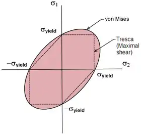
Plasticity theory depends upon a correct understanding of when yield will occur. A number of different models for stress distribution and approximations to the yield surface of plastic materials exist:[6]
Euler–Bernoulli beam equation

The Euler–Bernoulli beam equation defines the behaviour of a beam element (see below). It is based on five assumptions:
- Continuum mechanics is valid for a bending beam.
- The stress at a cross section varies linearly in the direction of bending, and is zero at the centroid of every cross section.
- The bending moment at a particular cross section varies linearly with the second derivative of the deflected shape at that location.
- The beam is composed of an isotropic material.
- The applied load is orthogonal to the beam's neutral axis and acts in a unique plane.
A simplified version of Euler–Bernoulli beam equation is:
Here is the deflection and is a load per unit length. is the elastic modulus and is the second moment of area, the product of these giving the flexural rigidity of the beam.
This equation is very common in engineering practice: it describes the deflection of a uniform, static beam.
Successive derivatives of have important meanings:
- is the deflection.
- is the slope of the beam.
- is the bending moment in the beam.
- is the shear force in the beam.
A bending moment manifests itself as a tension force and a compression force, acting as a couple in a beam. The stresses caused by these forces can be represented by:
where is the stress, is the bending moment, is the distance from the neutral axis of the beam to the point under consideration and is the second moment of area. Often the equation is simplified to the moment divided by the section modulus , which is . This equation allows a structural engineer to assess the stress in a structural element when subjected to a bending moment.
Buckling

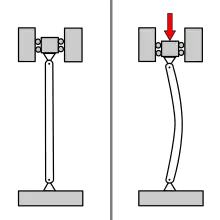
When subjected to compressive forces it is possible for structural elements to deform significantly due to the destabilising effect of that load. The effect can be initiated or exacerbated by possible inaccuracies in manufacture or construction.
The Euler buckling formula defines the axial compression force which will cause a strut (or column) to fail in buckling.
where
- = maximum or critical force (vertical load on column),
- = modulus of elasticity,
- = area moment of inertia, or second moment of area
- = unsupported length of column,
- = column effective length factor, whose value depends on the conditions of end support of the column, as follows.
- For both ends pinned (hinged, free to rotate), = 1.0.
- For both ends fixed, = 0.50.
- For one end fixed and the other end pinned, 0.70.
- For one end fixed and the other end free to move laterally, = 2.0.
This value is sometimes expressed for design purposes as a critical buckling stress.
where
- = maximum or critical stress
- = the least radius of gyration of the cross section
Other forms of buckling include lateral torsional buckling, where the compression flange of a beam in bending will buckle, and buckling of plate elements in plate girders due to compression in the plane of the plate.
References
- Melchers, R. E. (2002), "Structural Reliability Analysis and Prediction," 2nd Ed., John Wiley, Chichester, UK.
- Piryonesi, Sayed Madeh; Tavakolan, Mehdi (9 January 2017). "A mathematical programming model for solving cost-safety optimization (CSO) problems in the maintenance of structures". KSCE Journal of Civil Engineering. 21 (6): 2226–2234. doi:10.1007/s12205-017-0531-z.
- Dym, Clive L. (1997). Structural Modeling and Analysis. Cambridge University Press. p. 98. ISBN 0-521-49536-9.
- Heyman, Jacques (1998). Structural Analysis: A Historical Approach. Cambridge University Press. ISBN 0-521-62249-2.
- Nilson, Arthur H.; Darwin, David; Dolan, Charles W. (2004). Design of Concrete Structures. McGraw-Hill Professional. p. 486. ISBN 0-07-248305-9.
- Heyman, Jacques (1999). The Science of Structural Engineering. Imperial College Press. ISBN 1-86094-189-3.
- Castigliano, Carlo Alberto (translator: Andrews, Ewart S.) (1966). The Theory of Equilibrium of Elastic Systems and Its Applications. Dover Publications.
- Dym, Clive L. (1997). Structural Modeling and Analysis. Cambridge University Press. ISBN 0-521-49536-9.
- Dugas, René (1988). A History of Mechanics. Courier Dover Publications. ISBN 0-486-65632-2.
- Hewson, Nigel R. (2003). Prestressed Concrete Bridges: Design and Construction. Thomas Telford. ISBN 0-7277-2774-5.
- Heyman, Jacques (1998). Structural Analysis: A Historical Approach. Cambridge University Press. ISBN 0-521-62249-2.
- Heyman, Jacques (1999). The Science of Structural Engineering. Imperial College Press. ISBN 1-86094-189-3.
- Hognestad, E. A Study of Combined Bending and Axial Load in Reinforced Concrete Members. University of Illinois, Engineering Experiment Station, Bulletin Series N. 399.
- Jennings, Alan (2004) Structures: From Theory to Practice. Taylor & Francis. ISBN 978-0-415-26843-1.
- Leonhardt, A. (1964). Vom Caementum zum Spannbeton, Band III (From Cement to Prestressed Concrete). Bauverlag GmbH.
- MacNeal, Richard H. (1994). Finite Elements: Their Design and Performance. Marcel Dekker. ISBN 0-8247-9162-2.
- Mörsch, E. (Stuttgart, 1908). Der Eisenbetonbau, seine Theorie und Anwendung, (Reinforced Concrete Construction, its Theory and Application). Konrad Wittwer, 3rd edition.
- Nedwell, P.J.; Swamy, R.N.(ed) (1994). Ferrocement:Proceedings of the Fifth International Symposium. Taylor & Francis. ISBN 0-419-19700-1.
- Newton, Isaac; Leseur, Thomas; Jacquier, François (1822). Philosophiæ Naturalis Principia Mathematica. Oxford University.
- Nilson, Arthur H.; Darwin, David; Dolan, Charles W. (2004). Design of Concrete Structures. McGraw-Hill Professional. ISBN 0-07-248305-9.
- Rozhanskaya, Mariam; Levinova, I. S. (1996). "Statics" in Morelon, Régis & Rashed, Roshdi (1996). Encyclopedia of the History of Arabic Science, vol. 2-3, Routledge. ISBN 0-415-02063-8
- Schlaich, J., K. Schäfer, M. Jennewein (1987). "Toward a Consistent Design of Structural Concrete". PCI Journal, Special Report, Vol. 32, No. 3.
- Scott, Richard (2001). In the Wake of Tacoma: Suspension Bridges and the Quest for Aerodynamic Stability. ASCE Publications. ISBN 0-7844-0542-5.
- Turner, J.; Clough, R.W.; Martin, H.C.; Topp, L.J. (1956). "Stiffness and Deflection of Complex Structures". Journal of Aeronautical Science Issue 23.
- Virdi, K.S. (2000). Abnormal Loading on Structures: Experimental and Numerical Modelling. Taylor & Francis. ISBN 0-419-25960-0.
