Structural geology
Structural geology is the study of the three-dimensional distribution of rock units with respect to their deformational histories. The primary goal of structural geology is to use measurements of present-day rock geometries to uncover information about the history of deformation (strain) in the rocks, and ultimately, to understand the stress field that resulted in the observed strain and geometries. This understanding of the dynamics of the stress field can be linked to important events in the geologic past; a common goal is to understand the structural evolution of a particular area with respect to regionally widespread patterns of rock deformation (e.g., mountain building, rifting) due to plate tectonics.

Use and importance
The study of geologic structures has been of prime importance in economic geology, both petroleum geology and mining geology.[1] Folded and faulted rock strata commonly form traps that accumulate and concentrate fluids such as petroleum and natural gas. Similarly, faulted and structurally complex areas are notable as permeable zones for hydrothermal fluids, resulting in concentrated areas of base and precious metal ore deposits. Veins of minerals containing various metals commonly occupy faults and fractures in structurally complex areas. These structurally fractured and faulted zones often occur in association with intrusive igneous rocks. They often also occur around geologic reef complexes and collapse features such as ancient sinkholes. Deposits of gold, silver, copper, lead, zinc, and other metals, are commonly located in structurally complex areas.
Structural geology is a critical part of engineering geology, which is concerned with the physical and mechanical properties of natural rocks. Structural fabrics and defects such as faults, folds, foliations and joints are internal weaknesses of rocks which may affect the stability of human engineered structures such as dams, road cuts, open pit mines and underground mines or road tunnels.
Geotechnical risk, including earthquake risk can only be investigated by inspecting a combination of structural geology and geomorphology.[2] In addition, areas of karst landscapes which reside atop caverns, potential sinkholes, or other collapse features are of particular importance for these scientists. In addition, areas of steep slopes are potential collapse or landslide hazards.
Environmental geologists and hydrogeologists need to apply the tenets of structural geology to understand how geologic sites impact (or are impacted by) groundwater flow and penetration. For instance, a hydrogeologist may need to determine if seepage of toxic substances from waste dumps is occurring in a residential area or if salty water is seeping into an aquifer.
Plate tectonics is a theory developed during the 1960s which describes the movement of continents by way of the separation and collision of crustal plates. It is in a sense structural geology on a planet scale, and is used throughout structural geology as a framework to analyze and understand global, regional, and local scale features.[3]
Methods
Structural geologists use a variety of methods to (first) measure rock geometries, (second) reconstruct their deformational histories, and (third) estimate the stress field that resulted in that deformation.
Geometries
Primary data sets for structural geology are collected in the field. Structural geologists measure a variety of planar features (bedding planes, foliation planes, fold axial planes, fault planes, and joints), and linear features (stretching lineations, in which minerals are ductilely extended; fold axes; and intersection lineations, the trace of a planar feature on another planar surface).

Measurement conventions
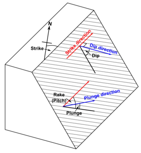
The inclination of a planar structure in geology is measured by strike and dip. The strike is the line of intersection between the planar feature and a horizontal plane, taken according to the right hand convention, and the dip is the magnitude of the inclination, below horizontal, at right angles to strike. For example; striking 25 degrees East of North, dipping 45 degrees Southeast, recorded as N25E,45SE.
Alternatively, dip and dip direction may be used as this is absolute. Dip direction is measured in 360 degrees, generally clockwise from North. For example, a dip of 45 degrees towards 115 degrees azimuth, recorded as 45/115. Note that this is the same as above.
The term hade is occasionally used and is the deviation of a plane from vertical i.e. (90°-dip).
Fold axis plunge is measured in dip and dip direction (strictly, plunge and azimuth of plunge). The orientation of a fold axial plane is measured in strike and dip or dip and dip direction.
Lineations are measured in terms of dip and dip direction, if possible. Often lineations occur expressed on a planar surface and can be difficult to measure directly. In this case, the lineation may be measured from the horizontal as a rake or pitch upon the surface.
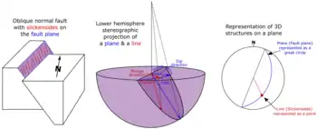
Rake is measured by placing a protractor flat on the planar surface, with the flat edge horizontal and measuring the angle of the lineation clockwise from horizontal. The orientation of the lineation can then be calculated from the rake and strike-dip information of the plane it was measured from, using a stereographic projection.
If a fault has lineations formed by movement on the plane, e.g.; slickensides, this is recorded as a lineation, with a rake, and annotated as to the indication of throw on the fault.
Generally it is easier to record strike and dip information of planar structures in dip/dip direction format as this will match all the other structural information you may be recording about folds, lineations, etc., although there is an advantage to using different formats that discriminate between planar and linear data.
Plane, fabric, fold and deformation conventions
The convention for analysing structural geology is to identify the planar structures, often called planar fabrics because this implies a textural formation, the linear structures and, from analysis of these, unravel deformations.
Planar structures are named according to their order of formation, with original sedimentary layering the lowest at S0. Often it is impossible to identify S0 in highly deformed rocks, so numbering may be started at an arbitrary number or given a letter (SA, for instance). In cases where there is a bedding-plane foliation caused by burial metamorphism or diagenesis this may be enumerated as S0a.
If there are folds, these are numbered as F1, F2, etc. Generally the axial plane foliation or cleavage of a fold is created during folding, and the number convention should match. For example, an F2 fold should have an S2 axial foliation.
Deformations are numbered according to their order of formation with the letter D denoting a deformation event. For example, D1, D2, D3. Folds and foliations, because they are formed by deformation events, should correlate with these events. For example, an F2 fold, with an S2 axial plane foliation would be the result of a D2 deformation.
Metamorphic events may span multiple deformations. Sometimes it is useful to identify them similarly to the structural features for which they are responsible, e.g.; M2. This may be possible by observing porphyroblast formation in cleavages of known deformation age, by identifying metamorphic mineral assemblages created by different events, or via geochronology.
Intersection lineations in rocks, as they are the product of the intersection of two planar structures, are named according to the two planar structures from which they are formed. For instance, the intersection lineation of a S1 cleavage and bedding is the L1-0 intersection lineation (also known as the cleavage-bedding lineation).
Stretching lineations may be difficult to quantify, especially in highly stretched ductile rocks where minimal foliation information is preserved. Where possible, when correlated with deformations (as few are formed in folds, and many are not strictly associated with planar foliations), they may be identified similar to planar surfaces and folds, e.g.; L1, L2. For convenience some geologists prefer to annotate them with a subscript S, for example Ls1 to differentiate them from intersection lineations, though this is generally redundant.
Stereographic projections

Stereographic projection is a method for analyzing the nature and orientation of deformation stresses, lithological units and penetrative fabrics wherein linear and planar features (structural strike and dip readings, typically taken using a compass clinometer) passing through an imagined sphere are plotted on a two-dimensional grid projection, facilitating more holistic analysis of a set of measurements. Stereonet[4] developed by Richard W. Allmendinger is widely used in the structural geology community.
Rock macro-structures
On a large scale, structural geology is the study of the three-dimensional interaction and relationships of stratigraphic units within terranes of rock or geological regions.
This branch of structural geology deals mainly with the orientation, deformation and relationships of stratigraphy (bedding), which may have been faulted, folded or given a foliation by some tectonic event. This is mainly a geometric science, from which cross sections and three-dimensional block models of rocks, regions, terranes and parts of the Earth's crust can be generated.
Study of regional structure is important in understanding orogeny, plate tectonics and more specifically in the oil, gas and mineral exploration industries as structures such as faults, folds and unconformities are primary controls on ore mineralisation and oil traps.
Modern regional structure is being investigated using seismic tomography and seismic reflection in three dimensions, providing unrivaled images of the Earth's interior, its faults and the deep crust. Further information from geophysics such as gravity and airborne magnetics can provide information on the nature of rocks imaged to be in the deep crust.
Rock microstructures
Rock microstructure or texture of rocks is studied by structural geologists on a small scale to provide detailed information mainly about metamorphic rocks and some features of sedimentary rocks, most often if they have been folded.
Textural study involves measurement and characterisation of foliations, crenulations, metamorphic minerals, and timing relationships between these structural features and mineralogical features.
Usually this involves collection of hand specimens, which may be cut to provide petrographic thin sections which are analysed under a petrographic microscope.
Microstructural analysis finds application also in multi-scale statistical analysis, aimed to analyze some rock features showing scale invariance.[5]
Kinematics
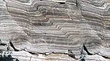
Geologists use rock geometry measurements to understand the history of strain in rocks. Strain can take the form of brittle faulting and ductile folding and shearing. Brittle deformation takes place in the shallow crust, and ductile deformation takes place in the deeper crust, where temperatures and pressures are higher.
Stress fields
By understanding the constitutive relationships between stress and strain in rocks, geologists can translate the observed patterns of rock deformation into a stress field during the geologic past. The following list of features are typically used to determine stress fields from deformational structures.
- In perfectly brittle rocks, faulting occurs at 30° to the greatest compressional stress. (Byerlee's Law)
- The greatest compressive stress is normal to fold axial planes.
Characterization of the mechanical properties of rock
The mechanical properties of rock play a vital role in the structures that form during deformation deep below the earth's crust. The conditions in which a rock is present will result in different structures that geologists observe above ground in the field. The field of structural geology tries to relate the formations that humans see to the changes the rock went through to get to that final structure. Knowing the conditions of deformation that lead to such structures can illuminate the history of the deformation of the rock.
Temperature and pressure play a huge role in the deformation of rock. At the conditions under the earth's crust of extreme high temperature and pressure, rocks are ductile. They can bend, fold or break. Other vital conditions that contribute to the formation of structure of rock under the earth are the stress and strain fields.
Stress-strain curve
Stress is a pressure, defined as a directional force over area. When a rock is subjected to stresses, it changes shape. When the stress is released, the rock may or may not return to its original shape. That change in shape is quantified by strain, the change in length over the original length of the material in one dimension. Stress induces strain which ultimately results in a changed structure.
Elastic deformation refers to a reversible deformation. In other words, when stress on the rock is released, the rock returns to its original shape. Reversible, linear, elasticity involves the stretching, compressing, or distortion of atomic bonds. Because there is no breaking of bonds, the material springs back when the force is released. This type of deformation is modeled using a linear relationship between stress and strain, i.e. a Hookean relationship.
Where σ denotes stress, denotes strain, and E is the elastic modulus, which is material dependent. The elastic modulus is, in effect, a measure of the strength of atomic bonds.
Plastic deformation refers to non-reversible deformation. The relationship between stress and strain for permanent deformation is nonlinear. Stress has caused permanent change of shape in the material by involving the breaking of bonds.
One mechanism of plastic deformation is the movement of dislocations by an applied stress. Because rocks are essentially aggregates of minerals, we can think of them as poly-crystalline materials. Dislocations are a type of crystallographic defect which consists of an extra or missing half plane of atoms in the periodic array of atoms that make up a crystal lattice. Dislocations are present in all real crystallographic materials.
Hardness
Hardness is difficult to quantify. It is a measure of resistance to deformation, specifically permanent deformation. There is precedent for hardness as a surface quality, a measure of the abrasiveness or surface-scratching resistance of a material. If the material being tested, however, is uniform in composition and structure, then the surface of the material is only a few atomic layers thick, and measurements are of the bulk material. Thus, simple surface measurements yield information about the bulk properties. Ways to measure hardness include:
- Mohs Scale
- Dorry abrasion test
- Deval abrasion test
- Indentation hardness
Indentation hardness is used often in metallurgy and materials science and can be thought of as resistance to penetration by an indenter.
Toughness
Toughness can be described best by a material's resistance to cracking. During plastic deformation, a material absorbs energy until fracture occurs. The area under the stress-strain curve is the work required to fracture the material. The toughness modulus is defined as:
Where is the ultimate tensile strength, and is the strain at failure. The modulus is the maximum amount of energy per unit volume a material can absorb without fracturing. From the equation for modulus, for large toughness, high strength and high ductility are needed. These two properties are usually mutually exclusive. Brittle materials have low toughness because low plastic deformation decreases the strain (low ductility). Ways to measure toughness include: Page impact machine and Charpy impact test
Resilience
Resilience is a measure of the elastic energy absorbed of a material under stress. In other words, the external work performed on a material during deformation. The area under the elastic portion of the stress-strain curve is the strain energy absorbed per unit volume. The resilience modulus is defined as:
where is the yield strength of the material and E is the elastic modulus of the material. To increase resilience, one needs increased elastic yield strength and decreased modulus of elasticity.
See also
References
- Russell, William L (1955). "1. Introduction". Structural Geology for Petroleum Geologists. New York: McGraw-Hill. p. 1.
- "Plate tectonics and people". USGS.
- Livaccari, Richard F.; Burke, Kevin; Scedilengör, A. M. C. (1981). "Was the Laramide orogeny related to subduction of an oceanic plateau?". Nature. 289 (5795): 276–278. Bibcode:1981Natur.289..276L. doi:10.1038/289276a0. S2CID 27153755.
- "Stereonet". Rick Allmendinger's Stuff. Retrieved 2022-12-23.
- V. Guerriero; et al. (2011). "Improved statistical multi-scale analysis of fractures in carbonate reservoir analogues". Tectonophysics. Elsevier. 504 (1): 14–24. Bibcode:2011Tectp.504...14G. doi:10.1016/j.tecto.2011.01.003. V. Guerriero; et al. (2009). "Quantifying uncertainties in multi-scale studies of fractured reservoir analogues: Implemented statistical analysis of scan line data from carbonate rocks". Journal of Structural Geology. Elsevier. 32 (9): 1271–1278. Bibcode:2010JSG....32.1271G. doi:10.1016/j.jsg.2009.04.016.
Further reading
- M. King Hubbert (1972). Structural Geology. Hafner Publishing Company.
- G.H. Davis and S.J. Reynolds (1996). The structural geology of rocks and regions (2nd ed.). Wiley. ISBN 0-471-52621-5.
- C.W. Passchier and R.A.J. Trouw (1998). Microtectonics. Berlin: Springer. ISBN 3-540-58713-6.
- B.A. van der Pluijm and S. Marshak (2004). Earth Structure - An Introduction to Structural Geology and Tectonics (2nd ed.). New York: W. W. Norton. p. 656. ISBN 0-393-92467-X.
- D.U Deere and R.P. Miller (1966). Engineering Classification and Index Properties for Intact Rock. Technical Report No AFWL-TR-65-116 Air Force Weapons Laboratory.
