American wire gauge
American wire gauge (AWG), also known as the Brown & Sharpe wire gauge, is a logarithmic stepped standardized wire gauge system used since 1857, predominantly in North America, for the diameters of round, solid, nonferrous, electrically conducting wire. Dimensions of the wires are given in ASTM standard B 258.[1] The cross-sectional area of each gauge is an important factor for determining its current-carrying ampacity.
Increasing gauge numbers denote decreasing wire diameters, which is similar to many other non-metric gauging systems such as British Standard Wire Gauge (SWG), but unlike IEC 60228, the metric wire-size standard used in most parts of the world. This gauge system originated in the number of drawing operations used to produce a given gauge of wire. Very fine wire (for example, 30 gauge) required more passes through the drawing dies than 0 gauge wire did. Manufacturers of wire formerly had proprietary wire gauge systems; the development of standardized wire gauges rationalized selection of wire for a particular purpose.
The AWG tables are for a single, solid and round conductor. The AWG of a stranded wire is determined by the cross-sectional area of the equivalent solid conductor. Because there are also small gaps between the strands, a stranded wire will always have a slightly larger overall diameter than a solid wire with the same AWG.
AWG is also commonly used to specify body piercing jewelry sizes (especially smaller sizes), even when the material is not metallic.[2]
Formulas
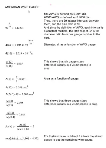
By definition, Nr. 36 AWG is 0.005 inches in diameter, and Nr. 0000 is 0.46 inches in diameter, or nearly half-an-inch. The ratio of these diameters is 1:92, and there are 40 gauge sizes from the smallest Nr. 36 AWG to the largest Nr. 0000AWG , or 39 steps. Each successive gauge number decreases the wire diameter by a constant factor. Any two neighboring gauges (e.g., AWG A and AWG B ) have diameters whose ratio (dia. B ÷ dia. A) is while for gauges two steps apart (e.g., AWG A, AWG B, and AWG C), the ratio of the C to A is about 1.122932 ≈ 1.26098 .

The diameter of an AWG wire is determined according to the following formula:

(where n is the AWG size for gauges from 36 to 0, n = −1 for Nr. 00, n = −2 for AWG 000, and n = −3 for AWG 0000. See rule below.[lower-alpha 1])
or equivalently:

The gauge number can be calculated from the diameter using the following formulas:[lower-alpha 3]
- Step 1
- Calculate the ratio of the wire's diameter to the standard gauge (AWG #36 )
- where the middle expression with is used if is measured in inches, and the right-hand expression with when is measured in millimeters.[lower-alpha 4]


- Step 2
- Calculate the American wire gauge number n using any convenient logarithm; pick any one of the following expressions in the last two columns of formulas to calculate n; notice that they differ in the choice of base of the logarithm, but otherwise are identical:
- In general, the calculation can be done using any base B strictly greater than zero.[lower-alpha 5]

and the cross-section area is

The standard ASTM B258-02 defines the ratio between successive sizes to be the 39th root of 92, or approximately 1.1229322.[3] ASTM B258-02 also dictates that wire diameters should be tabulated with no more than 4 significant figures, with a resolution of no more than 0.0001 inches (0.1 mils) for wires larger than Nr. 44 AWG, and 0.00001 inches (0.01 mils) for wires Nr. 45 AWG and smaller.
Very fat wires have gauge` sizes denoted by multiple zeros – 0, 00, 000, and 0000 – the more zeros, the larger the wire, starting with AWG 0. The two notations overlap when the 2 step formula for n , above, produces zero. In that case the gauge number n is zero, it's taken as-is. If n is a negative number, the gauge number is notated by multiple zeros, up to just under a half-inch; beyond that point, the “wire” may instead considered a copper bar or rod.[lower-alpha 1] The gauge can be denoted either using the long form with several zeros or the short form z "/0" called gauge "number of zeros/0" notation. For example 4/0 is short for AWG 0000. For an z /0 AWGwire, use the number of zeros and similarly in the above formulas. For instance, for AWG 0000 or 4/0, use


Rules of thumb
The sixth power of 39√92 is very close to 2,[4] which leads to the following rules of thumb:
- When the cross-sectional area of a wire is doubled, the AWG will decrease by 3 . (E.g. two AWG Nr. 14 wires have about the same cross-sectional area as a single AWG nr. 11 wire.) This doubles the conductance.
- When the diameter of a wire is doubled, the AWG will decrease by 6 . (E.g. AWG nr. 2 is about twice the diameter of AWG nr. 8 .) This quadruples the cross-sectional area and the conductance.
- A decrease of ten gauge numbers, for example from nr. 12 to nr. 2, multiplies the area and weight by approximately 10, and reduces the electrical resistance (and increases the conductance) by a factor of approximately 10.
- For the same cross section, aluminum wire has a conductivity of approximately 61% of copper, so an aluminum wire has nearly the same resistance as a copper wire smaller by 2 AWG sizes, which has 62.9% of the area.
- A solid round 18 AWG wire is about 1 mm in diameter.
- An approximation for the resistance of copper wire may be expressed as follows:
Approximate resistance of copper wire[5]: 27 AWG
numbermΩ/ft mΩ/m AWG
numbermΩ/ft mΩ/m AWG
numbermΩ/ft mΩ/m AWG
numbermΩ/ft mΩ/m 000 0.064 0.2 8 0.64 2 18 6.4 20 28 64 200 00 0.08 0.25 9 0.8 2.5 19 8 25 29 80 250 0 0.1 0.32 10 1 3.2 20 10 32 30 100 320 1 0.125 0.4 11 1.25 4 21 12.5 40 31 125 400 2 0.16 0.5 12 1.6 5 22 16 50 32 160 500 3 0.2 0.64 13 2 6.4 23 20 64 33 200 640 4 0.25 0.8 14 2.5 8 24 25 80 34 250 800 5 0.32 1.0 15 3.2 10 25 32 100 35 320 1,000 6 0.4 1.25 16 4 12.5 26 40 125 36 400 1,250 7 0.5 1.6 17 5 16 27 50 160 37 500 1,600
Tables of AWG wire sizes
The table below shows various data including both the resistance of the various wire gauges and the allowable current (ampacity) based on a copper conductor with plastic insulation. The diameter information in the table applies to solid wires. Stranded wires are calculated by calculating the equivalent cross sectional copper area. Fusing current (melting wire) is estimated based on 25 °C (77 °F) ambient temperature. The table below assumes DC, or AC frequencies equal to or less than 60 Hz, and does not take skin effect into account. "Turns of wire per unit length" is the reciprocal of the conductor diameter; it is therefore an upper limit for wire wound in the form of a helix (see solenoid), based on uninsulated wire.
| AWG | Diameter | Turns of wire, without insulation |
Area | Copper wire | |||||||||||
|---|---|---|---|---|---|---|---|---|---|---|---|---|---|---|---|
| Resistance per unit length[6] | Max I at 4 A/mm2 current density | Ampacity at temperature rating[lower-alpha 6] | Fusing current[9][10] | ||||||||||||
| 60 °C | 75 °C | 90 °C | Preece[11][12][13][14] | Onderdonk[15][14] | |||||||||||
| (in) | (mm) | (per in) | (per cm) | (kcmil) | (mm2) | (mΩ/m[lower-alpha 7]) | (mΩ/ft[lower-alpha 8]) | (A) | ≈10 s | 1 s | 32 ms | ||||
| 0000 (4/0) | 0.4600[lower-alpha 9] | 11.684[lower-alpha 9] | 2.17 | 0.856 | 212 | 107 | 0.1608 | 0.04901 | — | 195 | 230 | 260 | 3.2 kA | 33 kA | 182 kA |
| 000 (3/0) | 0.4096 | 10.405 | 2.44 | 0.961 | 168 | 85.0 | 0.2028 | 0.06180 | — | 165 | 200 | 225 | 2.7 kA | 26 kA | 144 kA |
| 00 (2/0) | 0.3648 | 9.266 | 2.74 | 1.08 | 133 | 67.4 | 0.2557 | 0.07793 | — | 145 | 175 | 195 | 2.3 kA | 21 kA | 115 kA |
| 0 (1/0) | 0.3249 | 8.251 | 3.08 | 1.21 | 106 | 53.5 | 0.3224 | 0.09827 | — | 125 | 150 | 170 | 1.9 kA | 16 kA | 91 kA |
| 1 | 0.2893 | 7.348 | 3.46 | 1.36 | 83.7 | 42.4 | 0.4066 | 0.1239 | — | 110 | 130 | 145 | 1.6 kA | 13 kA | 72 kA |
| 2 | 0.2576 | 6.544 | 3.88 | 1.53 | 66.4 | 33.6 | 0.5127 | 0.1563 | — | 95 | 115 | 130 | 1.3 kA | 10.2 kA | 57 kA |
| 3 | 0.2294 | 5.827 | 4.36 | 1.72 | 52.6 | 26.7 | 0.6465 | 0.1970 | — | 85 | 100 | 115 | 1.1 kA | 8.1 kA | 45 kA |
| 4 | 0.2043 | 5.189 | 4.89 | 1.93 | 41.7 | 21.2 | 0.8152 | 0.2485 | — | 70 | 85 | 95 | 946 A | 6.4 kA | 36 kA |
| 5 | 0.1819 | 4.621 | 5.50 | 2.16 | 33.1 | 16.8 | 1.028 | 0.3133 | — | — | — | — | 795 A | 5.1 kA | 28 kA |
| 6 | 0.1620 | 4.115 | 6.17 | 2.43 | 26.3 | 13.3 | 1.296 | 0.3951 | 53.2 | 55 | 65 | 75 | 668 A | 4.0 kA | 23 kA |
| 7 | 0.1443 | 3.665 | 6.93 | 2.73 | 20.8 | 10.5 | 1.634 | 0.4982 | 42.2 | — | — | — | 561 A | 3.2 kA | 18 kA |
| 8 | 0.1285 | 3.264 | 7.78 | 3.06 | 16.5 | 8.37 | 2.061 | 0.6282 | 33.5 | 40 | 50 | 55 | 472 A | 2.5 kA | 14 kA |
| 9 | 0.1144 | 2.906 | 8.74 | 3.44 | 13.1 | 6.63 | 2.599 | 0.7921 | 26.5 | 37 | 44 | 50 | 396 A | 2.0 kA | 11 kA |
| 10 | 0.1019 | 2.588 | 9.81 | 3.86 | 10.4 | 5.26 | 3.277 | 0.9989 | 21.0 | 30 | 35 | 40 | 333 A | 1.6 kA | 8.9 kA |
| 11 | 0.0907 | 2.305 | 11.0 | 4.34 | 8.23 | 4.17 | 4.132 | 1.260 | 16.7 | — | — | — | 280 A | 1.3 kA | 7.1 kA |
| 12 | 0.0808 | 2.053 | 12.4 | 4.87 | 6.53 | 3.31 | 5.211 | 1.588 | 13.2 | 20 | 25 | 30 | 235 A | 1.0 kA | 5.6 kA |
| 13 | 0.0720 | 1.828 | 13.9 | 5.47 | 5.18 | 2.62 | 6.571 | 2.003 | 10.5 | — | — | — | 198 A | 798 A | 4.5 kA |
| 14 | 0.0641 | 1.628 | 15.6 | 6.14 | 4.11 | 2.08 | 8.286 | 2.525 | 8.3 | 15 | 20 | 25 | 166 A | 633 A | 3.5 kA |
| 15 | 0.0571 | 1.450 | 17.5 | 6.90 | 3.26 | 1.65 | 10.45 | 3.184 | 6.6 | — | — | — | 140 A | 502 A | 2.8 kA |
| 16 | 0.0508 | 1.291 | 19.7 | 7.75 | 2.58 | 1.31 | 13.17 | 4.016 | 5.2 | — | — | 18 | 117 A | 398 A | 2.2 kA |
| 17 | 0.0453 | 1.150 | 22.1 | 8.70 | 2.05 | 1.04 | 16.61 | 5.064 | 4.2 | — | — | — | 99 A | 316 A | 1.8 kA |
| 18 | 0.0403 | 1.024 | 24.8 | 9.77 | 1.62 | 0.823 | 20.95 | 6.385 | 3.3 | 10 | 14 | 16 | 83 A | 250 A | 1.4 kA |
| 19 | 0.0359 | 0.912 | 27.9 | 11.0 | 1.29 | 0.653 | 26.42 | 8.051 | 2.6 | — | — | — | 70 A | 198 A | 1.1 kA |
| 20 | 0.0320 | 0.812 | 31.3 | 12.3 | 1.02 | 0.518 | 33.31 | 10.15 | 2.1 | 5 | 11 | — | 58.5 A | 158 A | 882 A |
| 21 | 0.0285 | 0.723 | 35.1 | 13.8 | 0.810 | 0.410 | 42.00 | 12.80 | 1.6 | — | — | — | 49 A | 125 A | 700 A |
| 22 | 0.0253 | 0.644 | 39.5 | 15.5 | 0.642 | 0.326 | 52.96 | 16.14 | 1.3 | 3 | 7 | — | 41 A | 99 A | 551 A |
| 23 | 0.0226 | 0.573 | 44.3 | 17.4 | 0.509 | 0.258 | 66.79 | 20.36 | 1.0 | — | — | — | 35 A | 79 A | 440 A |
| 24 | 0.0201 | 0.511 | 49.7 | 19.6 | 0.404 | 0.205 | 84.22 | 25.67 | 0.8 | 2.1 | 3.5 | — | 29 A | 62 A | 348 A |
| 25 | 0.0179 | 0.455 | 55.9 | 22.0 | 0.320 | 0.162 | 106.2 | 32.37 | 0.7 | — | — | — | 24 A | 49 A | 276 A |
| 26 | 0.0159 | 0.405 | 62.7 | 24.7 | 0.254 | 0.129 | 133.9 | 40.81 | 0.5 | 1.3 | 2.2 | — | 20 A | 39 A | 218 A |
| 27 | 0.0142 | 0.361 | 70.4 | 27.7 | 0.202 | 0.102 | 168.9 | 51.47 | 0.4 | — | — | — | 17 A | 31 A | 174 A |
| 28 | 0.0126 | 0.321 | 79.1 | 31.1 | 0.160 | 0.0810 | 212.9 | 64.90 | 0.3 | 0.83 | 1.4 | — | 14 A | 24 A | 137 A |
| 29 | 0.0113 | 0.286 | 88.8 | 35.0 | 0.127 | 0.0642 | 268.5 | 81.84 | 0.26 | — | — | — | 12 A | 20 A | 110 A |
| 30 | 0.0100 | 0.255 | 99.7 | 39.3 | 0.101 | 0.0509 | 338.6 | 103.2 | 0.20 | 0.52 | 0.86 | — | 10 A | 15 A | 86 A |
| 31 | 0.00893 | 0.227 | 112 | 44.1 | 0.0797 | 0.0404 | 426.9 | 130.1 | 0.16 | — | — | — | 9 A | 12 A | 69 A |
| 32 | 0.00795 | 0.202 | 126 | 49.5 | 0.0632 | 0.0320 | 538.3 | 164.1 | 0.13 | 0.32 | 0.53 | — | 7 A | 10 A | 54 A |
| 33 | 0.00708 | 0.180 | 141 | 55.6 | 0.0501 | 0.0254 | 678.8 | 206.9 | 0.10 | — | — | — | 6 A | 7.7 A | 43 A |
| 34 | 0.00630 | 0.160 | 159 | 62.4 | 0.0398 | 0.0201 | 856.0 | 260.9 | 0.08 | 0.18 | 0.3 | — | 5 A | 6.1 A | 34 A |
| 35 | 0.00561 | 0.143 | 178 | 70.1 | 0.0315 | 0.0160 | 1079 | 329.0 | 0.06 | — | — | — | 4 A | 4.8 A | 27 A |
| 36 | 0.00500[lower-alpha 9] | 0.127[lower-alpha 9] | 200 | 78.7 | 0.0250 | 0.0127 | 1361 | 414.8 | 0.05 | — | — | — | 4 A | 3.9 A | 22 A |
| 37 | 0.00445 | 0.113 | 225 | 88.4 | 0.0198 | 0.0100 | 1716 | 523.1 | 0.04 | — | — | — | 3 A | 3.1 A | 17 A |
| 38 | 0.00397 | 0.101 | 252 | 99.3 | 0.0157 | 0.00797 | 2164 | 659.6 | 0.032 | — | — | — | 3 A | 2.4 A | 14 A |
| 39 | 0.00353 | 0.0897 | 283 | 111 | 0.0125 | 0.00632 | 2729 | 831.8 | 0.025 | — | — | — | 2 A | 1.9 A | 11 A |
| 40 | 0.00314 | 0.0799 | 318 | 125 | 0.00989 | 0.00501 | 3441 | 1049 | 0.020 | — | — | — | 1 A | 1.5 A | 8.5 A |
| AWG | Diameter | Turns of wire, without insulation |
Area | Copper wire | |||||||||||
| Resistance per unit length[6] | Max I at 4 A/mm2 current density | Ampacity at temperature rating[lower-alpha 10] | Fusing current[9][10] | ||||||||||||
| 60 °C | 75 °C | 90 °C | Preece[11][12][13][14] | Onderdonk[15][14] | |||||||||||
| (in) | (mm) | (per in) | (per cm) | (kcmil) | (mm2) | (mΩ/m[lower-alpha 7]) | (mΩ/ft[lower-alpha 8]) | (A) | ≈10 s | 1 s | 32 ms | ||||
- For example, for the gauge used "AWG 0", as-is; for the gauge is either "00" or "2/0"; for either "000" or "3/0"; either "0000" or "4/0"; and so on. The number of zeros, and the number n are off by one.
- Note that, to the a little error in the last digits,
-
The logarithm base 92 can be computed using any other logarithm, such as common or natural logarithm, using where B is any base for a logarithm – any number bigger than zero. Common values of “ B ” are 10 (base 10 logarithms, usually shown as just
logon the keys of most calculators; a more explicit notation is to write out ). Likewise, most hand calculators show the natural logarithm asln, or more explicitly as where e is Euler's number, Any logarithm will do, including exotic logarithms such as the binary or base-two logarithm the only caveat is that the same logarithm must be used throughout any one calculation. - Since exactly, by definition of the inch: defines the value of the inch. The two expressions for the ratio always produce the same number (when the correct units of measure are used for in each). Note that the units of divide out, as do producing a "pure number".
- That is: You can use any logarithm you want, or have available, so long as the logarithm's base (B) is the same in both the numerator and denominator for any one calculation.
- For enclosed wire at 30 °C ambient,[7] with given insulation material temperature rating, or for single unbundled wires in equipment for 16 AWG and smaller.[8]
- or, equivalently, Ω/km
- or, equivalently, Ω/kft
- Exactly, by definition
- For enclosed wire at 30 °C ambient,[7] with given insulation material temperature rating, or for single unbundled wires in equipment for 16 AWG and smaller.[8]


In the North American electrical industry, conductors larger than 4/0 AWG are generally identified by the area in thousands of circular mils (kcmil), where 1 kcmil = 0.5067 mm2. The next wire size larger than 4/0 has a cross section of 250 kcmil. A circular mil is the area of a wire one mil in diameter. One million circular mils is the area of a circle with 1,000 mil (1 inch) diameter. An older abbreviation for one thousand circular mils is MCM.
Stranded wire AWG sizes
AWG gauges are also used to describe stranded wire. The AWG gauge of a stranded wire represents the sum of the cross-sectional areas of the individual strands; the gaps between strands are not counted. When made with circular strands, these gaps occupy about 25% of the wire area, thus requiring the overall bundle diameter to be about 13% larger than a solid wire of equal gauge.
Stranded wires are specified with three numbers, the overall AWG size, the number of strands, and the AWG size of a strand. The number of strands and the AWG of a strand are separated by a slash. For example, a 22 AWG 7/30 stranded wire is a 22 AWG wire made from seven strands of 30 AWG wire.
As indicated in the Formulas and Rules of Thumb sections above, differences in AWG translate directly into ratios of diameter or area. This property can be employed to easily find the AWG of a stranded bundle by measuring the diameter and count of its strands. (This only applies to bundles with circular strands of identical size.) To find the AWG of 7-strand wire with equal strands, subtract 8.4 from the AWG of a strand. Similarly, for 19-strand subtract 12.7, and for 37 subtract 15.6. See the Mathcad worksheet illustration of this straightforward application of the formula.
Measuring strand diameter is often easier and more accurate than attempting to measure bundle diameter and packing ratio. Such measurement can be done with a wire gauge go-no-go tool such as a Starrett 281 or Mitutoyo 950–202, or with a caliper or micrometer.
Nomenclature and abbreviations in electrical distribution
Alternative ways are commonly used in the electrical industry to specify wire sizes as AWG.
- 4 AWG (proper)
- #4 (the number sign is used as an abbreviation of "number")
- № 4 (the numero sign is used as an abbreviation for "number")
- No. 4 (an approximation of the numero is used as an abbreviation for "number")
- No. 4 AWG
- 4 ga. (abbreviation for "gauge")
- 000 AWG (proper for large sizes)
- 3/0 (common for large sizes) Pronounced "three-aught"
- 3/0 AWG
- #000
Pronunciation
AWG is colloquially referred to as gauge and the zeros in large wire sizes are referred to as aught /ˈɔːt/. Wire sized 1 AWG is referred to as "one gauge" or "No. 1" wire; similarly, smaller diameters are pronounced "x gauge" or "No. x" wire, where x is the positive-integer AWG number. Consecutive AWG wire sizes larger than No. 1 wire are designated by the number of zeros:
- No. 0, often written 1/0 and referred to as "one aught" wire. In the math formulas, this value is 0.
- No. 00, often written 2/0 and referred to as "two aught" wire. In the math formulas, this value is −1.
- No. 000, often written 3/0 and referred to as "three aught" wire. In the math formulas, this value is −2.
and so on.
See also
- Wire gauge comparison chart
- French gauge
- Brown & Sharpe
- Circular mil, North American Electrical industry standard for wires larger than 4/0.
- Birmingham Wire Gauge
- Stubs Iron Wire Gauge
- Jewelry wire gauge
- Body jewelry sizes
- Electrical wiring
- Number 8 wire, a term used in the New Zealand vernacular
References
- "ASTM B258-14 Standard Specification for Standard Nominal Diameters and Cross-sectional Areas of AWG Sizes of Solid Round Wires Used as Electrical Conductors". West Conshohocken: ASTM International. Archived from the original on 22 July 2014. Retrieved 22 March 2015.
- SteelNavel.com Body Piercing Jewelry Size Reference — illustrating the different ways that size is measured on different kinds of jewelry
- Standard Specification for Standard Nominal Diameters and Cross-Sectional Areas of AWG Sizes of Solid Round Wires Used as Electrical Conductors (Report). 2008. p. 4. ASTM B258-02.
- The result is roughly 2.0050, or one-quarter of one percent higher than 2
-
Copper Wire Tables. U.S. Bureau of Standards (Technical report). Circular of the Bureau of Standards. Vol. 31. Stratton, S.W. director of the N.B.S. in office on publication (3rd ed.). United States Department of Commerce. 1 October 1914 – via archive.org.
{{cite techreport}}: CS1 maint: others (link) -
Figure for solid copper wire at 68 °F, (Not in accordance to NEC Codebook 2014 Ch. 9, Table 8) computed based on 100% IACS conductivity of 58.0 MS/m, which agrees with multiple sources:
- Lund, Mark. "American Wire Gauge table and AWG Electrical Current Load Limits". Powerstream.com. Retrieved 2008-05-02. (although the ft/m conversion seems slightly erroneous)
- Belden Master Catalog, 2006, although data from there for gauges 35 and 37–40 seems obviously wrong.
- NFPA 70 National Electrical Code 2014 Edition Archived 2008-10-15 at the Wayback Machine. Table 310.15(B)(16) (formerly Table 310.16) page 70-161, "Allowable ampacities of insulated conductors rated 0 through 2000 volts, 60°C through 90°C, not more than three current-carrying conductors in raceway, cable, or earth (directly buried) based on ambient temperature of 30°C." Extracts from NFPA 70 do not represent the full position of NFPA and the original complete Code must be consulted. In particular, the maximum permissible overcurrent protection devices may set a lower limit.
- "Table 11: Recommended Current Ratings (Continuous Duty) for electronic equipment and chassis wiring". Reference Data for Engineers: Radio, Electronics, Computer and Communications (7th ed.). pp. 49–16.
- Computed using equations from Beaty, H. Wayne; Fink, Donald G., eds. (2007), The Standard Handbook for Electrical Engineers (15th ed.), McGraw Hill, pp. 4–25, ISBN 978-0-07-144146-9
- Brooks, Douglas G. (December 1998), "Fusing Current: When Traces Melt Without a Trace" (PDF), Printed Circuit Design, 15 (12): 53
- "II. On the heating effects of electric currents". Proceedings of the Royal Society of London. 36 (228–231): 464–471. 31 December 1883. doi:10.1098/rspl.1883.0133. S2CID 135649550.
- "I. On the heating effects of electric currents. No. II". Proceedings of the Royal Society of London. 43 (258–265): 280–295. 31 December 1888. doi:10.1098/rspl.1887.0133. S2CID 136941916.
- "IV. On the heating effects of electric currents. No. III". Proceedings of the Royal Society of London. 44 (266–272): 109–111. 31 December 1888. doi:10.1098/rspl.1888.0006. S2CID 103775782.
- Brooks, Douglas G.; Adam, Johannes (29 June 2015), "Who Were Preece and Onderdonk?", Printed Circuit Design and Fab
- Stauffacher, E. R. (June 1928), "Short-time Current Carrying Capacity of Copper Wire" (PDF), General Electric Review, 31 (6)
Further reading
- File:Gauge Chart.pdf