3

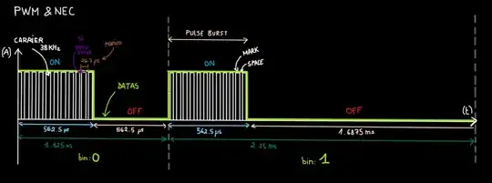
I try to understand how to generate IR carrier frequency with the raspberry and how PWM and NEC work visually. I learn PWM but I cannot find any explication of duty cycle. Ok it's a percentage of HIGH state on 1 cycle or 1 period or 1Hz ... But what is the require duty-cycle for IR LED and what is related to ? I have create this picture :

enter image description here

I have also read this dicussion : Notes-on:-Pulse-Width-Modulation-(PWM) , control-hardware-pwm-frequency and driving-pwm-output-frequency

I have written a script capable to find GPIO PWMC and PWMR configuration values, then the output of my script is:

Enter the frequency in Hz : 38000
Enter the tolerance in % : .1
Tolerance: 0.1% (38 Hz)
PWMC:5, PWMR:101, PWM_RESOLUTION:0.3 us/unit, PWM_PERIOD:26.3 us, PWM_FREQ:38019.8 Hz       DIFF:+19.8 Hz  
PWMC:101, PWMR:5, PWM_RESOLUTION:5.3 us/unit, PWM_PERIOD:26.3 us, PWM_FREQ:38019.8 Hz       DIFF:+19.8 Hz  
PWMC:505, PWMR:1, PWM_RESOLUTION:26.3 us/unit, PWM_PERIOD:26.3 us, PWM_FREQ:38019.8 Hz      DIFF:+19.8 Hz

PWMC must be only an predefined even number ? ( In this case my script is wrong) The nearest divider for a 38KHz carrier seems to be BCM2835_PWM_CLOCK_DIVIDER_512 = 512, /*!< 512 = 37.5kHz */
Ephemeral
  • 2,057
  • 4
  • 18
  • Some time ago I started learning about IR and googled some references. One instructable is every educational. You might find the it and other IR modules references in my answer to the following question (https://raspberrypi.stackexchange.com/questions/99823/using-pi-to-control-a-button-on-a-hdmi-switcher ). I have also bought those cheapy modules but have not yet started testing. I still have not started learning LIRC. If you proposed some newbie DIY test, I am interested to try. – tlfong01 Jul 08 '19 at 12:15
  • @tlfong01, Thank for your reply. Yes the schematic on your link (from instructable universal command) is good. But how the carrier frequency is generate ... I think (for the moment) : gpio mode 1 pwm; gpio pwm-ms; gpio pwmc 101; gpio pwmr 5; ... and then set the duty cycle about 50% (I actually search the command) . – Ephemeral Jul 08 '19 at 12:46
  • you might to read my other answers to questions about PWM below. But I am thinking of using IR modules to generate 38kHz signals instead of DIYing using GPIOs. But I have not yet started. I am waiting for Rpi4 and buster. (1) ( https://raspberrypi.stackexchange.com/questions/97999/sg-5010-servo-360-degree-modification-not-working ) (2) ( https://raspberrypi.stackexchange.com/questions/99408/pin-powered-pi-crashes-when-servos-move ) (3) ( https://raspberrypi.stackexchange.com/questions/99315/run-the-program-in-the-laptop-and-use-the-raspberry-gpios ) – tlfong01 Jul 08 '19 at 13:03
  • Actually I know very little about the NEC code. I read that it is PDM (Pulse Distance Modulation). I need to think hard to decode such modulation. (1) NEC Protocol ( https://www.sbprojects.net/knowledge/ir/nec.php ) (2) IR Remote Control Tool (NEC) 2015mar25 ( http://www.technoblogy.com/show?UVE ) (3) IR Remote Control Receiver 2015apr03 ( http://www.technoblogy.com/show?V6F ) – tlfong01 Jul 08 '19 at 13:42

1 Answers1

1

A 38 KHz PWM carrier has 38000 cycles per second. Each cycle takes 1 million / 38 thousand microseconds, so approximately 26 microseconds per cycle.

The dutycycle is the percentage time the PWM signal is high per cycle.

Infrared devices use mark space PWM rather than balanced PWM. All you need to know is that mark space means the signal goes from high to low just once per cycle.

For infrared signals I tend to use 50% dutycycle, so on for 13 µs then off for 13 µs. Commercial devices (i.e. remote controls) tend to use something like 30% dutycycle, so on for 8 µs, off for 18 µs. They only do that to save power so I'd stick to 50%.

joan
  • 67,803
  • 5
  • 67
  • 102
  • Thank you very much for your explanation. I also wrote this question on electronic.stackexchange and got pretty much the same answer. I understand the cycle of service ... but I do not understand why, for example, you choose 50% and not 80% or 85%, etc. the voltage of the LED? I can read that a 50% duty cycle would be 3.3V (VMax) / 2 = 1.65V but for me (IMHO) it's not 1.65V it's 3.3V on 1/2 cycle ... this is not the same because 3.3V is reached I am confused in what I can read on the Internet. – Ephemeral Jul 08 '19 at 08:57
  • I haven't really thought about that. I never even considered using a higher dutycycle. I suppose I stopped thinking about it once it was working. – joan Jul 08 '19 at 09:00
  • Thank you. the LED remains more or less lit for a long time depending on the duty cycle? The LED flash at 38 KHz for 562.5us for the NEC protocol, what is called PULSE BURST I think. The LED flashes at 38 KHz but the duty cycle does not affect the carrier frequency then it's not a problem. But I would like to understand what is happening. My last thought is that the LED remains lit for a long time thanks to the 'carrier frequency' (its blinking determinate by duty cycle) and then remains more or less lit depending on the protocol used (eg NEc, RC-5 ...)? – Ephemeral Jul 08 '19 at 09:15
  • I have never heard that the dutycycle varies according to the protocol being used. I have read a bit about this and think I would have remembered if that was the case. By the way, pigpio waves are pretty good for transmitting IR signals. If you are familiar with Python have a look at http://abyz.me.uk/rpi/pigpio/examples.html#Python_irrp_py – joan Jul 08 '19 at 09:19