2

In order to power a Raspberry Pi Zero W, I'm using the 7805 converter to lower the ~11.4V from a LiPo Battery to 5V. The resulted voltage is about 4.96V.

The Raspberry Pi starts to boot for about 20 seconds, then it reboots.

I'm also using the recommended capacitors for the 7805.

There are no peripherals connected, only ssh/spi/i2c enabled.

Where should I look? Thanks!

Cosmin Mihai
  • 300
  • 5
  • 17
  • 1
    Good old 7805 is now a bad engineering choice, and damages Rpi users' reputation. Get a US$2 only LM2596 adjustable output DC-DC module, and set output to 5.25V. https://fr.aliexpress.com/item/32340998757.html?spm=a2g0o.productlist.0.0.256e3e88gCpJXL&algo_pvid=748d370d-d656-464b-b720-96fe03d75f05&algo_expid=748d370d-d656-464b-b720-96fe03d75f05-23&btsid=7dced05a-ab35-4a80-b345-ed7be63675ab&ws_ab_test=searchweb0_0,searchweb201602_9,searchweb201603_52 – tlfong01 Aug 06 '19 at 00:59
  • Yep! Buck converter (step-down converter) that is a DC-to-DC switching power converter. LM2596. They must drop voltage 1.1V or greater. 13.4V Optima AGM Car Battery, my unmarked 11.4V lipo, 2500C?, or a few 9V batteries in parallel. It handles the voltage change and sends out a smooth 5.04V (mb I should increase to 5.25v) that I have it tuned to. They can bought for as cheap as $8 for 12 of them on Amazon. Adjusting voltage on the variable resistor can be a pain. Digital ones are nicer and give voltage and amperage readings. If they have two solder points on each corner, use the outer-most. – TamusJRoyce Aug 06 '19 at 01:12

2 Answers2

2

The Foundation recommendations claim the Typical bare-board active current consumption for the Pi ZeroW is 150mA so it should work (depending on the battery).

However you are throwing away more than 50% of the battery power, which will be dissipated as heat which may cause the regulator to shutdown (again depending on the heatsink capability).

Use a switch-mode power module instead.

Milliways
  • 54,718
  • 26
  • 92
  • 182
2

The 7805 is a rather poor choice for this task since it is a so called linear voltage regulator. This means that it has no choice but to convert the voltage drop into heat. In this case 11.4 V - 5 V = 6.4 V. In other words, the regulator is going to produce more heat than the Pi itself and sucking your LiPO battery empty at the same time.

According to the datasheet and assuming the TO-220 package without heat sink has a thermal resistance junction-ambient (R_thJA) of 50 K/W (and even lower values for other packages such as D2PAK, DPAK, and TO-220FP). With P_D = (T_J(max) – T_A) / R_thJA and at an ambient temperature (T_A) of 25°C and the maximum junction temperature (T_J(max)) of 125°C - where the internal thermal-overload protection should kick in - a maximum power dissipation (PD) of 1.67 W is possible, which would be reached at about 260 mA. Besides wasting energy - not a preferable thing for a mobile application - operating the regulator at a higher temperature can affect reliability.

Now Power consumption of Pi Zero W? suggests the the Pi Zero W with WiFi enabled should consume less than that 260 mA which indicates it should be possible to run the Pi with this setup. Luckily the effect is rather simple to test - just check the temperature of the regulator. Warning, might be hot...

Possible (short term) solutions:

  1. add a heat sink to reduce R_thJA and get some more headroom
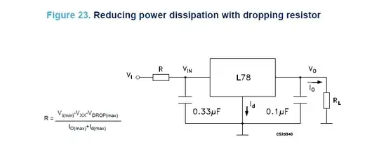
  2. reducing power dissipation with dropping resistor according to this circuit (note a required high power rating of the resistor, which will now share the burden with the regulator), (source):

enter image description here

Better (long term) solution:

  1. go for a switching regulator, i.e. a step-down UBEC
Ghanima
  • 15,578
  • 15
  • 58
  • 113