4

I have a Raspberry Pi 3b and wired to a 4 port relay I got from Amazon:
https://www.amazon.com/JBtek-Channel-Module-Arduino-Raspberry/dp/B00KTEN3TM/

Everything is working, but it seems backwards to me. First I set the modes to 'out' for all 4 of the GPIO ports I'm using. I'm using the following pins because they're close to each other on the pi, and issuing these commands to set up the ports properly:

gpio -g mode 26 out
gpio -g mode 13 out
gpio -g mode 6 out
gpio -g mode 5 out

From what I read, I should issue a '1' to turn them on, and a '0' to turn them off. But this seems to be reversed from what I'm seeing. If I issue a '1', nothing happens. If I issue a '0' they turn on. This turns them all on:

gpio -g write 26 0
gpio -g write 13 0
gpio -g write 6 0
gpio -g write 5 0

After that, I can issue a '1' to turn them off.
Is this normal behavior?
Ghanima
  • 15,578
  • 15
  • 58
  • 113
Jessica 6
  • 193
  • 2
  • 7
  • Duplicate of https://raspberrypi.stackexchange.com/questions/45406/controlling-switching-on-off-devices-via-relay-board – Milliways Oct 03 '19 at 23:50
  • NOTE There are man questions about this (or similar modules) from Amazon. Most fond they can't even be turned off by the Pi. They are a poor design (see https://raspberrypi.stackexchange.com/a/100014/8697) and they apply 5V to the GPIO which risks damaging the Pi. – Milliways Oct 04 '19 at 02:54

4 Answers4

3

Yes, many relays are low-On, high-Off.

It is normal.

CoderMike
  • 6,381
  • 1
  • 9
  • 15
2

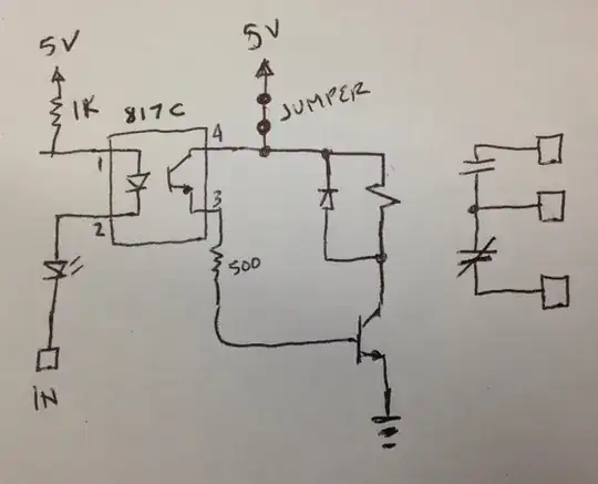
Considering the hand-drawn schematics available at the product page linked in the question, it is clear that the circuit is "active low". That is, the coil of the relays is energized if the input is low. The controlled contacts however are two-way contacts so that it is possible to either break or make a contact when either energizing or de-energizing the coil. If possible it is however advisable to chose the configuration in which the coil is energized the least amount of time.

enter image description here

(source: https://www.amazon.com/dp/B00KTEN3TM/ posted by Granpinos, Jul 06, 2015)

Ghanima
  • 15,578
  • 15
  • 58
  • 113
1

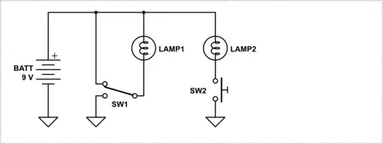
Here is how it works in simple terms.

Consider the following schematic.

Applying a LOW to a lamps turns it on.

It is sometimes referred to as "active low" signal.

schematic

simulate this circuit – Schematic created using CircuitLab

jsotola
  • 531
  • 1
  • 5
  • 11
1

Use a diode with

gpio(-) and relay input(+) if it doesn't work then reverse the diode connection. The gpio only supply 3.3 volt. Maybe this one will solve. While using nodemcu I faced the same problem.

Sohan Arafat
  • 1,770
  • 1
  • 9
  • 37