1

I have been using raspberry pi for my home automation project. To control 12v power, I use 5v relay low triggering to turn on or off the power. My coding and connection work fine. Problem is reliability of 5v relay. It is so frustrating to find 5v relay being broken and not working anymore. If there are someone who have recommendation of reliable 5v relay, please let me know. Price does not much matter.

Thank you all in advance.

  • Well, official Rpi tutorial sites and shops do recommend industrial grade relays, instead of unreliable eBay, perhaps 10 times more expensive than hobbyist grades. Official Rpi distributors such as Fxyz and E123 also sell industrial grade stuff, You can actually ask more for medical or mission critical specs. I used to play with miJ Nabc relays which are popular in our local building automation projects. – tlfong01 Dec 28 '19 at 02:20
  • What have you tried? What is the "load" you're switching - is it inductive? What is "low triggering"? If "price does not matter", you should look at some of the [JAN-qualified relays that Teledyne makes](https://www.teledynerelays.com/Datasheets/EMR%20Selection%20Guide.pdf). But if you have chronic failures in your `el cheapo` relays, I'll guess there's another problem. – Seamus Dec 28 '19 at 02:23
  • The official Rpi or MagPi recommending shops sell PiFace relays at around 27 pounds. You can find more references of industrial grade relays in the appendix section of my answer to the following question: https://raspberrypi.stackexchange.com/questions/99988/how-to-wire-a-raspberry-pi-to-a-16-channel-relay-module-it-wont-work. Happy relaying. Cheers. – tlfong01 Dec 28 '19 at 02:25

2 Answers2

4

The GPIO on a RPi are 3.3Vdc. If you are using this to drive a 5Vdc coil on a relay, then this is most likely the source of your issues. Relay coils have several specifications including the minimum required current to switch over the contacts, coil holding current (current required to hold the contact's state), and drop out voltage which is the voltage at which the coil will drop out. When you run the relay at 3.3V it may work, but you are also drawing a lot more current than the windings were designed for. My guess is you are burning out the coil.

What you should be doing is using a darlington transistor pair in between the GPIO output of the raspberry pi and the relay coil. The transistor pair acts to bridge the gap between the two different voltages. You can use the 5Vdc power available on the Pi to help drive the circuit. Here are links to a few sites that can give you a head start.

https://learn.adafruit.com/transistors-101/darlington-pairs

https://microcontrollerslab.com/introduction-uln2803-features/

In future, can you be more specific when describing your problem? How did you wire everything together? This will possibly help you get a good answer.

mike
  • 111
  • 1
  • 7
1

Some Comments:

@mike's answer is correct. I'll add this:

  1. The "reliability problem" may be in your design, not the relay.
  2. You've given us no specifications on your relay, so we don't know if you've chosen properly.
  3. Depending on the current required for the coil relay, a small bipolar npn transistor may work perfectly well.

An Answer:

Here's a schematic showing how to connect the components:

schematic

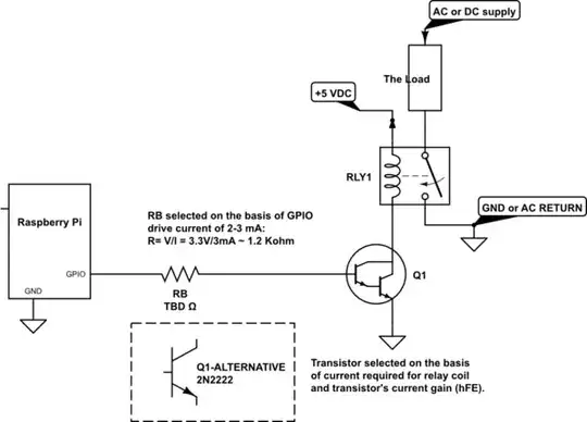
simulate this circuit – Schematic created using CircuitLab

Calculations and Explanations

In general, I feel the current draw from a GPIO pin should be limited to 2-3 mA (Here's why).

I also feel that Bipolar transistors are the best choice for interfacing to the RPi's GPIO because they are current driven. FETs and MOSFETs are voltage driven, and require gate drive voltages on the order of 7 VDC to minimize drain-to-source voltage drop. Bipolars are almost always the best choice for RPi projects!

Given that the transistor's base current drive will be limited to 2-3 mA, selection of a proper transistor is straightforward. Referring to the schematic above, calculate the minimum dc current gain (hFE) as follows:

hFE,min = (Relay Coil Current) / 2.5mA

For example, if a relay needs 100mA of current through the coil to close (or open) the relay's contacts, then a transistor with a minimum dc current gain (hFE,min) of 40 is required. There are many small signal transistors that will meet that requirement; e.g. the workhorse 2N2222 transistor. Better still, the 2N2222 (and improved 2N2222A) are cheap and readily available.

Seamus
  • 18,728
  • 2
  • 27
  • 57
  • 2
    Heck, without knowing his current or isolation requirements, he may be able to skip the relay altogether, and just use a transistor to control his 12v power. – Glen Yates Feb 11 '20 at 22:38
  • 1
    @GlenYates: That's a good point! But I've thought for a while I'd like to create this answer; the question about driving relays and using MOSFETs comes up frequently here. – Seamus Feb 12 '20 at 03:25