2

I am a beginner when it comes to electronics so I would appreciate your help with a simple project I am working on and have been struggling with for several days.

The idea is that I have a PIR Sensor outputting to GPIO 24 on my Pi. Via a python script, I would like to switch on a 12-volt LED strip with its own external power supply. I am able to see when motion is detected via the script, so that is working fine. The issue however is that I am not able to properly use my mosfets to act as a switch. In order to take it step by step, for now I am trying to output signal to my mosfet Gate via GPIO 24, and manually alter the PWM via terminal (instead of using the PIR output).

My scheme is similar to this: https://screen.sh/cAaSbZiM - however not using the battery, and using the GPIO 24 output instead of PIR.

I have tried this with a IRLB8721 mosfet, but realized it needs a higher voltage than what the GPIO can provide. The most suitable one I could find then was the IRF3205, seeing that it is used more frequently with Raspberry PI/Arduino applications, but unfortunately this is also not working. It seems like my GPIO voltage is still too low.

Alternatively I have a couple of 2N3904 transistors available but I am not entirely sure how I can use these without frying them.

I have noticed that when using the IRLB8721, my LEDs are always on, and I am not able to switch them off. I did make sure not to mix up the Drain and Source, yet still not working.

Could you please guide me in the right direction? I am not able to get any other components for another week, so I am stuck with a diode, couple of 1kOhm resistors, and these 3 types of transistors/mosfets/ Is there anything I can do to fix this?

I have looked this up extensively and tried it on my breadboards but with no success. Only lead I have is pointing to a fairchild mosfet which I am not able to get to for weeks.

Thank you.
Milliways
  • 54,718
  • 26
  • 92
  • 182
  • 1
    The Pi seems to be irrelevant to the question which is really about electronics. – joan May 22 '20 at 21:18
  • 1
    Hi @Orange Orange, Welcome and nice to meet you. You are asking too many questions at a time. Let me try to entertain some. (1) It is not a good idea to use Rpi power rail pin or GPIO pin to power supply the LED strip which might take huge surge currents. Better use the batteries as suggested in the tutorial. Power MOSFETs can drive big currents and there are low trig, yes, GPIO pin trigger versions, but for newbies, NPN BJT such as 2N2222 can usually do the job well. I vaguely remember 2N3904 is similar to 2N2222, but takes less current. Perhaps I can check it out & come back to you later. – tlfong01 May 23 '20 at 01:34
  • You might like to read the following power MOSFET Q&A:https://raspberrypi.stackexchange.com/questions/94031/power-mosfet-driving-big-motor-problem. To summarize my answer there: IRF540N can only be triggered by gate voltage > 5V. But ***IRL540N*** is the new low trig version, and can activate by Rpi GPIO, though I still recommend 2N2222 for your low power apps. WARNING: No guarantee no nothing won't melt down or blow up. – tlfong01 May 23 '20 at 01:39
  • More about low trig power MOSFETs, in case you don't mind reading long, boring stories: "Low Trig Power MOSFET Q&A - 2019feb19": https://www.raspberrypi.org/forums/viewtopic.php?f=91&t=232753&p=1431718&hilit=IRL540N+tlfong01#p1431718. The long story includes ***Optical isolated control circuits***, which is what the EE pro guys usually use. Happy learning. Cheers. – tlfong01 May 23 '20 at 01:46
  • I read your question again and found you saying about "manual PWM". I am not sure what you mean by that, and so I might misinterpret the big picture and your requirements. Please feel free to point out my misunderstandings, and I can suggest other turnarounds. Cheers. – tlfong01 May 23 '20 at 02:00
  • The 2N3904 transistors are perfect as long as long as you don't need more than about 100mA load current. In any event, you should stick with bipolar transistors - using MOSFETs is NOT your best choice because the GPIO pins are not up to the task - their ability to drive MOSFET gates is *marginal* at best. A schematic in your question would be very helpful also - here's how to [add a schematic to your question](https://raspberrypi.meta.stackexchange.com/questions/2074/how-do-i-add-a-schematic-to-my-question) – Seamus May 24 '20 at 04:52
  • Please post *your* schematic, not just some schematic which you don't actually use. – Dmitry Grigoryev May 26 '20 at 12:51

1 Answers1

3

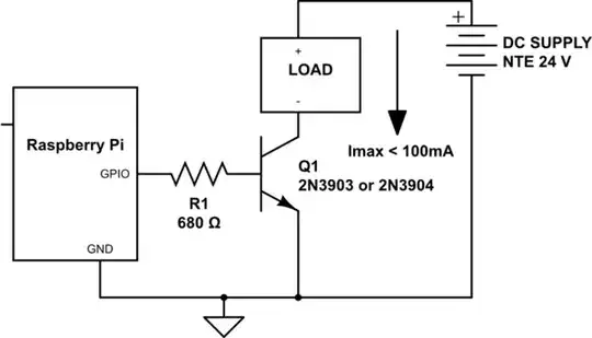
You didn't specify your load current requirements. This is a critical piece of information to select a proper transistor to switch your load. Once you learn what your load is, here's a rough guide to transistor selection for the RPi:

Low-side Switching - 0-24 VDC, 0-100mA:

schematic

simulate this circuit – Schematic created using CircuitLab

Low-side Switching - 0-24 VDC, 0-300mA:

  • Change Q1 to 2N2222A
  • Change Imax to: < 300mA
  • Change R1 to 330 Ohms

Low-side Switching - 0-48 VDC, 0-2 Amps:

  • Change Q1 to 2N6039G
  • Change DC SUPPLY to: NTE 48V
  • Change Imax to: < 2 Amps
  • Change R1 to: 680 Ohms

GPIO V-I characteristics defined in CM Datasheet

Seamus
  • 18,728
  • 2
  • 27
  • 57