I have connected a relay to BCM 14 and by setting its output to HIGH I can turn it on, making a 220V bulb to turn on.
I use for that the following python instructions:
GPIO.setmode(GPIO.BCM)
GPIO.setup(14, GPIO.OUT)
GPIO.output(14, GPIO.HIGH)
However, if I power off the pi, the bulb remains powered on, and obviously I can't control it anymore.
After restarting the pi, the gpio readall outputs:
+-----+-----+---------+------+---+---Pi 2---+---+------+---------+-----+-----+
| BCM | wPi |   Name  | Mode | V | Physical | V | Mode | Name    | wPi | BCM |
+-----+-----+---------+------+---+----++----+---+------+---------+-----+-----+
|     |     |    3.3v |      |   |  1 || 2  |   |      | 5v      |     |     |
|   2 |   8 |   SDA.1 | ALT0 | 1 |  3 || 4  |   |      | 5v      |     |     |
|   3 |   9 |   SCL.1 | ALT0 | 1 |  5 || 6  |   |      | 0v      |     |     |
|   4 |   7 | GPIO. 7 |   IN | 1 |  7 || 8  | 1 | ALT0 | TxD     | 15  | 14  | <<<< Bulb Relay
|     |     |      0v |      |   |  9 || 10 | 0 | ALT0 | RxD     | 16  | 15  |
|  17 |   0 | GPIO. 0 |   IN | 0 | 11 || 12 | 0 | IN   | GPIO. 1 | 1   | 18  |
|  27 |   2 | GPIO. 2 |   IN | 0 | 13 || 14 |   |      | 0v      |     |     |
|  22 |   3 | GPIO. 3 |   IN | 0 | 15 || 16 | 0 | IN   | GPIO. 4 | 4   | 23  |
|     |     |    3.3v |      |   | 17 || 18 | 0 | IN   | GPIO. 5 | 5   | 24  |
|  10 |  12 |    MOSI | ALT0 | 0 | 19 || 20 |   |      | 0v      |     |     |
|   9 |  13 |    MISO | ALT0 | 0 | 21 || 22 | 0 | IN   | GPIO. 6 | 6   | 25  |
|  11 |  14 |    SCLK | ALT0 | 0 | 23 || 24 | 1 | OUT  | CE0     | 10  | 8   |
|     |     |      0v |      |   | 25 || 26 | 1 | OUT  | CE1     | 11  | 7   |
|   0 |  30 |   SDA.0 |   IN | 1 | 27 || 28 | 1 | IN   | SCL.0   | 31  | 1   |
|   5 |  21 | GPIO.21 |   IN | 1 | 29 || 30 |   |      | 0v      |     |     |
|   6 |  22 | GPIO.22 |   IN | 1 | 31 || 32 | 0 | IN   | GPIO.26 | 26  | 12  |
|  13 |  23 | GPIO.23 |   IN | 0 | 33 || 34 |   |      | 0v      |     |     |
|  19 |  24 | GPIO.24 |   IN | 0 | 35 || 36 | 0 | IN   | GPIO.27 | 27  | 16  |
|  26 |  25 | GPIO.25 |   IN | 0 | 37 || 38 | 0 | IN   | GPIO.28 | 28  | 20  |
|     |     |      0v |      |   | 39 || 40 | 0 | IN   | GPIO.29 | 29  | 21  |
+-----+-----+---------+------+---+----++----+---+------+---------+-----+-----+
| BCM | wPi |   Name  | Mode | V | Physical | V | Mode | Name    | wPi | BCM |
+-----+-----+---------+------+---+---Pi 2---+---+------+---------+-----+-----+
So, even after the pi turns back on, the bulb remains turned on anyways until my script runs and when GPIO.setup(14, GPIO.OUT) is executed, the bulb turns off.
I would like to turn off the bulb if the pi goes down (it shuts down/disconnects from the internet – but that is another case I will treat in my script etc).
Should I use other pins for relays? Should I inverse the relay usage (LOW for ON and HIGH for OFF)?
I cannot figure this out and it is a little bit because sometimes the pi disconnects and I have to manually stop the electricity of the bulb.
By using BCM 8 (OUT, 1 by default, after restart), and using LOW output to turn on the relay, the bulb is turned off after restart, but obviously the issue is that as long the pi is completely disconnected from electricity, the relay close the circuit of the bulb.
In short I have the following cases/problems:
BCM USED   DEFAULT STATE  RELAY ON   PROBLEM
14         ALT0 1         HIGH       Bulb remains turned on after restart,
                                     until I set the STATE to OUT 0
8          OUT 1          LOW        Bulb turns on when pi is disconnected
Expected scenario: always turn off the bulb when the pi disconnects, turn on the bulb only from the script
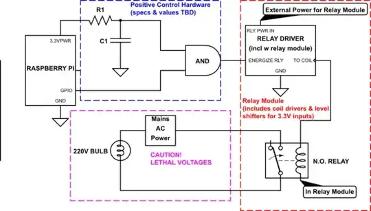
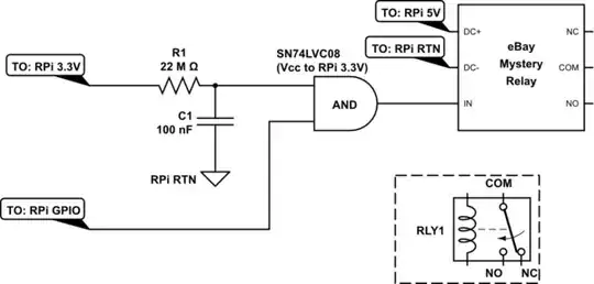
The circuit is very simple: I have a one channel relay that has a switch that can reverse the relay action. This is another question I have asked to see how to use the relay without the pi: https://electronics.stackexchange.com/q/301932/85944
 +---<--5V Transformer--------------------220V SOCKET
 |                                           |   |
Pi ---- [5v] ----- [(DC+)         COM]-------/   \------[ LIGHT ]
   ---- [0v] ----- [(DC-)  RELAY   NC]------------------[ BULB  ]
   ---- [BCM14] -- [(IN )          NO]