0

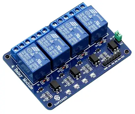
I've found a 5v relay board which is twice cheaper in comparaison with a board with 40 pin stacking header.

relay board

I can wire the Pi to the relay board using jumper cables but it look like messy.

My wish is to plug the Pi to the relay board but the problem is that the relay pin are GND | IN1 | IN2 | IN3 | VCC while on the Pi the 5v pins are followed by a GND, 3 GPIO then an other GND.

So is it possible to change the first GND to act as a GPIO? Or maybe there is a connector which may suit the need ?
buildog
  • 161
  • 6
  • Hi #builddog, @Carlton' suggestion is good. In case you would consider cheaper solutions, you might like to read my old answer on HAT workarounds: How to tap / tee / fork the Rpi GPIO pins covered / blocked by a HAT / pHAT / bonnet? https://raspberrypi.stackexchange.com/questions/104705/how-to-tap-tee-fork-the-rpi-gpio-pins-covered-blocked-by-a-hat-phat-bo. Happy hacking. Cheers. – tlfong01 Jun 16 '20 at 02:18
  • I think [this](https://raspberrypi.stackexchange.com/a/99480/33476) may be of interest to you, unless of course you already tried out your board and it works. – Dmitry Grigoryev Jun 30 '20 at 12:19

2 Answers2

2

This will require you to modify the traces on the pi's PCB. While it is possible it is not recommended. If looks concern you you would be better to get a case for the pi and relay.

Jake
  • 89
  • 10
2

You could use something like the Perma-Proto HAT to make an adapter between the Pi and the relay board. Use the regular 40-pin header to connect the Proto to the Pi, then solder on a custom 6-pin header to the Proto to mate with the relay. This would make the package a bit thicker, but would avoid wires and maybe you could use the Proto for other components as well.

Carlton
  • 136
  • 4