2

i am trying to connect two devices via UART to a raspberry 4. one being a stepper driver (i dont need much throughput), one being an image sensor (the higher the baud rate is i can get, the better). both are currently connected via USB-to-serial dongles, which i want to get rid of to get a better fit with the box it's housed in. i would be very happy if i could these to the pi using the 40-pin-header instead.

i have gone through what little documentation i could find, my config.txt looks like this (only the last two added by me):

dtparam=audio=on
[pi4]
dtoverlay=vc4-fkms-v3d
max_framebuffers=2
[all]
#enable_uart=1
dtoverlay = disable-bt
dtoverlay=uartx

and listing my serial devices looks like this:

root@raspberrypi:/home/pi# ls -la /dev/serial*
lrwxrwxrwx 1 root root 5 Jun  6 08:13 /dev/serial0 -> ttyS0
lrwxrwxrwx 1 root root 7 Jun  6 08:13 /dev/serial1 -> ttyAMA0

i have read this: Where are the uarts on the raspberry pi 4?

which states that there are more available PL011 UART ports - i take it that those could be used for my purpose, but they are not visible to the OS ... do i have to set them up from python with something like wiringpi? or is there another configuration that i missing?
rmalchow
  • 171
  • 5
  • 2
    You might like to read my old posts on how to use multiple UART ports on Rpi USB and on board: (1) https://penzu.com/journals/18951407/58119498, (2) https://raspberrypi.stackexchange.com/questions/96184/rpi-to-arduino-serial-uart-communication-tutorial. Cheers. – tlfong01 Jun 06 '21 at 08:11
  • 2
    néih hóu. from the second post (and the links therein), i learned a lot of little things. thank you very much for that. however, the first link only points to a login page on penzu, and the second one (as far as i can see) does not contain anything about getting two serial ports on the 40pin. i am beginning to suspect that i am missing something important ... – rmalchow Jun 06 '21 at 08:30
  • 3
    Have you read through either the raspberrypi.org web site documentation for config.txt or /boot/overlays/README ? – joan Jun 06 '21 at 08:39
  • @rmalchow, Ah, I gave you the wrong link. My apologies. Please try this one: https://penzu.com/public/b94e6b30, and let me know if it still don't work. Actually I have a couple more similar answers, mostly on other applications, eg. SIM etc. Please feel free to ask me more newbie questions. – tlfong01 Jun 06 '21 at 08:42
  • 2
    @joan such a polite way of saying "it's right there in the documentation, you idiot" :) but it _did_ help me to figure it out: it is dtoverlay=uart[X] where "X" is the number of the UART. also, tlfong's link spells it out. thank you! :) – rmalchow Jun 06 '21 at 08:51
  • 2
    @tlfong01 would you care to write a proper answer, so i can upvote you? if you don't feel like doing this, i'll do it myself. just so this answer is easier to find for the next person. – rmalchow Jun 06 '21 at 08:52
  • @rmalchow, Thank you for your kindness. I would prefer you to to skim my answers and try my suggestions, then share your experiences by writing your your own answer here, so that other newbies might follow. Actually I often do this, because this way newbies can learn deeper and remember harder. Here is an example, also on UART: (4) How can Rpi4B use UART to read and analyze received data at a 3DR FPV Air Radio Module? (Q&A) https://raspberrypi.stackexchange.com/questions/105223/how-can-rpi4b-use-uart-to-read-and-analyze-received-data-at-a-3dr-fpv-air-radio/105489#105489. /to continue, ... – tlfong01 Jun 06 '21 at 09:04
  • (5) How can Rpi4B use UART to read and analyze received data at a 3DR FPV Air Radio Module? (Chat) https://chat.stackexchange.com/rooms/100706/discussion-on-question-by-thelazy-how-can-rpi4b-use-uart-to-read-and-analyze-rec. Happy learning. Cheers. – tlfong01 Jun 06 '21 at 09:05
  • The linked Answer https://raspberrypi.stackexchange.com/a/107780/8697 contains a detailed answer and extracts from the Foundation documentation. – Milliways Jun 06 '21 at 09:18
  • @milliways yes, it does contain parts of the solution - however, i think the question there isn't great, and although the relevant documentation is cited, the problem being discussed is something different. in fact - i did see that post in my searches, but from reading the first part, i was unaware that is actually contained the solution to my problem. i tried to give another summary of the situation here now, in the hope that it is a bit easier to find ... – rmalchow Jun 06 '21 at 09:27
  • 1
    Does this answer your question? [Where are the uarts on the raspberry pi 4?](https://raspberrypi.stackexchange.com/questions/104464/where-are-the-uarts-on-the-raspberry-pi-4) – Dougie Jun 14 '21 at 00:06
  • @Dougie it kind of did - as you can see, my own answer below quotes that one quite a bit. my problem was that my understanding of how these ports work was completely wrong, so i tried to summarize what i learned below, adding the missing links that threw me off initially. – rmalchow Jun 14 '21 at 07:23

1 Answers1

5

so where was one big misunderstandings. thanks to @joan for pointing to the docs and @tlfong01 for their link to their article:

https://penzu.com/public/b94e6b30

essentially, on the raspberry 4, there are 6 UARTs available, but two of them use the same pins by default (board pin 8 and 10). additional UARTs can be enabled one-by-one, doing so eats into the available GPIO pins.

uarts are enabled through separate "dtoverlay=" entries in

/boot/config.txt

so, all on looks like this:

dtoverlay=uart5
dtoverlay=uart4
droverlay=uart3
dtoverlay=uart2
dtoverlay=uart1

these are mostly off, in favour of having the corresponding pins configured as "regular" GPIO pins. once enabled, they will appear as

/dev/ttyAMA[0,1,2 etc]

this thread here with contributions by @joan and @milliways has some details on the default pins:

Where are the uarts on the raspberry pi 4?

and the README on overlays

here: https://github.com/raspberrypi/firmware/blob/master/boot/overlays/README

or on the pi at: /boot/overlays/README

has some additional details on available configuration options, e.g.:

Name:   uart1
Info:   Change the pin usage of uart1
Load:   dtoverlay=uart1,<param>=<val>
Params: txd1_pin                GPIO pin for TXD1 (14, 32 or 40 - default 14)

        rxd1_pin                GPIO pin for RXD1 (15, 33 or 41 - default 15)

my setup is now like this:

dtoverlay=uart1
dtoverlay=uart5
dtoverlay=uart4

and my loopback test:

import serial
import time
test_string = "[serial port test]".encode('utf-8')
port_list = ["/dev/ttyAMA0","/dev/ttyAMA1","/dev/ttyAMA2","/dev/ttyAMA3","/dev/ttyAMA4" ]
for port in port_list:
  ok = False
  try:
    buff = bytearray(len(test_string))
    serialPort = serial.Serial(port, 115200, timeout = 2, writeTimeout = 2)
    bytes_sent = serialPort.write(test_string)
    time.sleep(1)
    bytes_read = serialPort.readinto(buff)
    ok = bytes_read == bytes_sent
    serialPort.close()
  except IOError:
    pass
  print("port %s is %s" % (port, "OK" if ok else "NOT OK"))

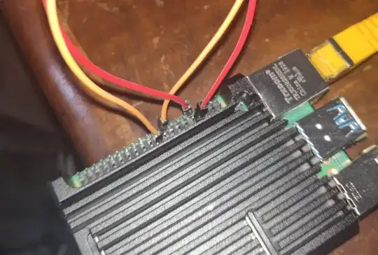
with the the RX/TX pairs for 4 and 5 bridged like this:

enter image description here

gives me the expected results.

Where are the uarts on the raspberry pi 4?

rmalchow
  • 171
  • 5
  • 2
    Many thanks for your answer. Your explanation is concise and clear, and your loopback test program is professional, comparing with my long winded newbie level demo programs. Cheers – tlfong01 Jun 06 '21 at 10:20