2

As title states, I am taking my first steps into electric circuits and microcontrollers, so I apologize in advance if my question is not clear or does not make much sense.

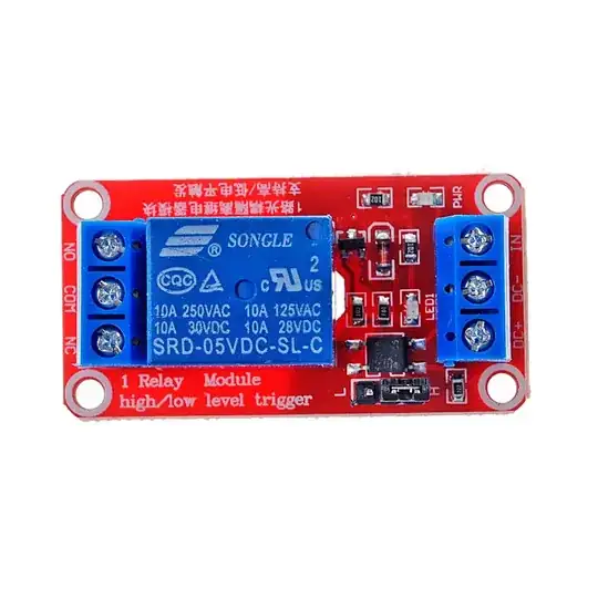
I am trying to control several (3 for now, I am aiming 8) relays modules (picture below), by using a raspberry pi zero W. I tried to power the relay by using an external 5v power source (phone charger + and - to DC+ and DC-) and connect the IN to the GPIO pin but it didn't work. Then I tried to power the relay directly with the board (5V to DC+ and GND to DC-) and now it works properly. Why is that? I started to read about the functioning of 5v relay modules here but I found discordant opinions on whether it is safe to connect the relays directly to the board, and as far as I understood it depends on how much current in mA the relay is drawing. Some customers posted this in the comment section under the same board I purchased: quiescent current (to 5 V): approx. 3 mA working current (to 5 V): approx. 75 mA control current (at 5 V on the optocoupler): approx. 1.7 mA

Which is the one I have to check? working current or control current? or both?

Also, could be that since I connected the DC- to the negative wire (and not to GND on the board) the reason why it did not work with the external power supply?

What is the risk of using the relay module directly wired with the board? I red that I could connect the GPIOs to a transistor uln2803 to increase the voltage going into the IN but I have no clue how to do it and what difference it makes. Also,I am planning to control 220v devices with some of these relays.

p.s. the relay board is set to HIGH at the moment.

sorry for the confusion but I am in the low point of the learning curve still XD

enter image description here

UPDATE: I found that for this problem some people uses this transistor for interfacing the Pi with the relay INs:

ULN 2803A STM EIGHT DARLINGTON ARRAYS

Features: EIGHTDARLINGTONS WITHCOMMONEMITTERS OUTPUT CURRENT TO 500 mA OUTPUT VOLTAGE TO50 V INTEGRAL SUPPRESSIONDIODES VERSIONS FOR ALL POPULARLOGIC FAMILIES OUTPUT CAN BE PARALLELED INPUTS PINNED OPPOSITE OUTPUTS TO SIMPLIFYBOARDLAYOUT

Why it does say up to 50V? how do I regulate the output voltage? In this way there would be no risk of current going "back" to the Pi from the relay?
  • 2
    When using the external power supply did you connect the grounds together? – Steve Robillard Nov 23 '21 at 15:32
  • 1
    Do you mean the GND of the Pi with the DC- of the relay? No, I simply connected the GPIO to the IN and powered separately the relay. – Loris Capria Nov 23 '21 at 15:49
  • 4
    Then you need to have a ground between the Pi and the relay; do it the same way you did when powering directly (GRD to DC-), just don't connect DC+. Note without this you are increasing the risk of more serious consequences than just "not working" (eg. "pi will never work again"). – goldilocks Nov 23 '21 at 16:02
  • 1
    Ouch. Good to know. Is there any issue with connecting then one GPIO to the IN of the relay without an interfacing transistor? or the module contains the required "protections" already? – Loris Capria Nov 23 '21 at 16:06
  • 2
    Relay modules have been discussed here in detail ([example](https://raspberrypi.stackexchange.com/questions/92299/4-relay-board-weird-behavior)), please search before posting. – Dmitry Grigoryev Nov 23 '21 at 16:23
  • 1
    Yeah I actually searched a lot about that. But as I wrote, there is contrasting information. And where alternatives are proposed, each of those are different. I am sorry but I lack the technical competence to understand those differences. Happy to learn if there is a thread (I did not find it yet) where it explains in easy terms what to do and how. (e.g. in your link there is a circuit scheme explaining and I do not understand a single piece of it) – Loris Capria Nov 23 '21 at 16:30
  • 1
    It would probably be easier if you asked a detailed question about some specific thing which you don't understand by including a reference and quote of the source you don't understand ("What does this mean? I think ... but I am not sure"). – goldilocks Nov 23 '21 at 16:45
  • 1
    " I red that I could connect the GPIOs to a transistor uln2803 to increase the voltage going into the IN but I have no clue how to do it and what difference it makes" From my question. – Loris Capria Nov 23 '21 at 16:54
  • 3
    Does this answer your question? [Can you use a 5V Relay Module with the Pi?](https://raspberrypi.stackexchange.com/questions/118116/can-you-use-a-5v-relay-module-with-the-pi) – Milliways Nov 23 '21 at 23:05
  • (1) Your module is jumper select High/Low trigger one. Setting to High level trigger, then for 3V3 Rpi, it is asking for potential trouble. ***If you set Low, you should have better luck.*** (2) ULN2803 is overkill. (3) You can find a guide to your H/L selectable module in ***Part D of my answer*** to the following EESE Q&A: How to properly use a relay module with JD-VCC from Arduino/Raspberry? - EESE, Asked 1 year, 5 months ago Active 3 months ago Viewed 15k times, https://electronics.stackexchange.com/questions/505318/how-to-properly-use-a-relay-module-with-jd-vcc-from-arduino-raspberry. – tlfong01 Nov 24 '21 at 08:42
  • Wow thanks! I will have a read on that! I will read the threads you posted above and see if I can clarify such points. What do you mean with ULN2803 is "overkill"? – Loris Capria Nov 25 '21 at 10:54
  • I need this information for a custom shield I ordered for my Pi. I contacted the seller but he said <>. Now I am a bit confused though. – Loris Capria Nov 25 '21 at 10:54

0 Answers0