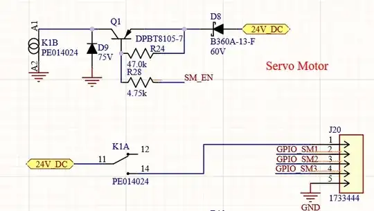
I'm designing a PCB to mount and interact with a raspberry pi4. One of the things I need it to do is drive a 24V relay. This circuit has worked great with some controllers I've used where the outputs are hardwired as outputs (they can never be inputs). I want to use this same circuit but am concerned as to what would happen if the driving GPIO (SM_EN) was inadvertently set to input, causing it to read voltage with nearly zero current draw. This would cause no v_drop across the resistors and the PI would see nearly 24V. This toast the PI's GPIO, correct? Can anyone recommend some protective circuit or settings on the PI that would prevent this from happening? Its weird to think of a circuit node as being able to read and set voltages. But, I'd imagine a simple OpAmp buffer circuit would do the trick?
Asked
Active
Viewed 100 times
1 Answers
1
DO NOT do this. If you connect this to a Pi it will put 24V on the GPIO and destroy the Pi.
Using a PNP transistor just makes everything more difficult.
You could control the device with an external transistor. This is similar to Use a 5V Relay Module with the Pi Addendum, although the voltages are different, the principle and problem are the same.
Milliways
- 54,718
- 26
- 92
- 182
-
Thank you! I was being told by a senior level staff designer that this is fine, to use the circuit, and that I'm over thinking it. I also realized even if this PI GPIO was set as an output the fact that it is a PNP means the BJT will never change states. I either need less than 24V or 24V to change states. The other controller this was used on ran on 24V logic states (which makes sense as to why it worked on a different controller previously, but wont with the PI). I appreciate your confirmation. – BBridges Dec 07 '21 at 01:40
