1

I am struggling with the same latching relay featured here:

Command/control latching relay using gpio pin only

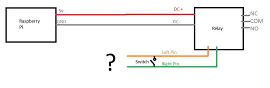
Edit: somehow there's been confusion, I'm trying to activate this, the latching relay that's mentioned right in the question linked above:

https://www.amazon.com/dp/B00LW2VLS0/ref=cm_sw_r_apan_glt_i_0ZYT8N7F9TJ9MBG57SPE?_encoding=UTF8&psc=1

Like the original author, I noticed the left pin, when attached to the ground, will trigger the relay. However I want to be able to control it from both the raspberry pi, and a momentary switch (which I want to work even while the pi is off) .

Currently I'm here:

But I'm having a hard time understanding the answer. I get that I not only need, but would like more information on this subject. I plan to take a course for that at my University (even though it's not relevant to my degree).

For now, could you explain like I'm Five what I need to do to accomplish this? If I had to take an educated guess, this is what I would end up with:

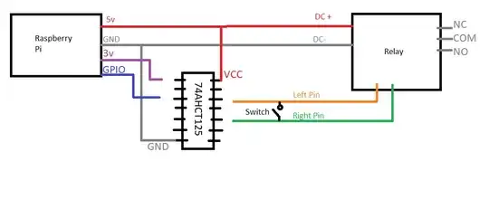
I have no limit on how many connections I can make, like the op in the post above seemed to, as they'll be in close proximity of each other. I just need the gpio to be able to trigger the latching relay by any means necessary essentially (and hopefully not kill the pi).

If you could sketch up what you would have me do, that would be greatly appreciated. I'm aware tlfong01 did just that in the post, but it has me lost. it looks like in his drawing, GND is going to 3Y according to pinouts on this? (Rhetorical) https://cdn-shop.adafruit.com/product-files/1787/1787AHC125.pdf I'm not even sure if that's right, or what 3Y is, and could very much use a... 5 year old friendly drawing if that's not asking too much.

Evan S
  • 21
  • 3
  • start with this ... think about `how would you connect two switches, so that either switch would activate the relay?` – jsotola Jan 22 '22 at 00:38
  • I'm trying to control the latching relay featured here: https://raspberrypi.stackexchange.com/questions/98133/command-control-latching-relay-using-gpio-pin-only or if you prefer the Amazon link: https://www.amazon.com/dp/B00LW2VLS0/ref=cm_sw_r_apan_glt_i_0ZYT8N7F9TJ9MBG57SPE?_encoding=UTF8&psc=1 – Evan S Jan 22 '22 at 01:19
  • Also, that not sure how you think the linked question Has "nothing to do with a latching relay", the title is literally "Command/control latching relay using gpio pin only"? Regardless, the link you provided has 1 "in" pin per relay, mine has 2, if it were different, I would know what to do, but I couldn't find one that was 5v – Evan S Jan 22 '22 at 01:23
  • Also, for the "how would you connect two switches, so that either switch would activate the relay?", that would be relevant if 1 active signal is how I would activate the relay, but it's 2 pins instead of 1 – Evan S Jan 22 '22 at 01:28
  • 1
    You appear to be correct. The device you have appears to be a latching relay. Unfortunately the link is devoid of any meaningful data so we can't say how to use it. None of the answers in the link appears to address this either. My guess is that one press would turn it on a second off. You need to determine the actual circuitry on the relay as this is not in the data. This, unfortunately, is common for many Chinese devices. – Milliways Jan 22 '22 at 02:37
  • You have it right. So there's a "Test button" on it, one push, and it's "on" (the Normally open/Common are connected), push again and it's "Off" (Normally closed, and Common are connected). the two pins are set in a way where you could connect the wires to your own button, and have the same result. briefly connect the two pins, and it toggles the latching relay "on" or "off". alternatively, I found if you just connect the left pin (view picture, Orange) to ground, it will also toggle it "on" or "off". Essentially I just need the orange pin to briefly flow through ground, and then stop I think – Evan S Jan 22 '22 at 03:33
  • 2
    NOTE You should NOT put detail into Comments. You should edit your Question so any others can tell what you are asking. – Milliways Jan 22 '22 at 04:07
  • Please [edit] your question and place *all of the additional details from the comments* into the question, so that readers don't have to trawl through numerous comments in order to get the full picture. Comments are general ethereal in nature and tend to get deleted. – Greenonline Aug 20 '22 at 23:30
  • To Evan S: My situation is similar. The reason I am thinking a lathing relay, is that it will be active for like 12 hours, and I was thinking it a possible problem to keep the GPIO pin high for that long, plus I want this setup to last for years. – Randy Bryant Aug 20 '22 at 22:00
  • The answers here were okay, but for some reason they seem to always request more info. I got a better answer from reddit with the same question. I added it to the answers. I'm not sure using a latching relay is better than using a high gpio, but I would look into using a mechanical relay if you want it active for 12 hours (I think thats what it's called at least?) Some relays will reset when they lose power. With a mechanical it should keep its position despite the temporary outage. May be worth researching at least – Evan S Aug 21 '22 at 23:21

3 Answers3

1

After reviewing your question, it seems to me you're looking for a User's Guide or specification sheet on a particular device you have bought. By now, it may have occurred to you that hardware components without manufacturer's documentation is a fine recipe for failure and frustration, but not much else. The answer is simple: Don't buy stuff without documentation. My recommendation is that you return this item to the vendor for a full refund.

That said, latching relays are very useful devices, and worth learning about. You may learn a little bit by reviewing this Q&A that used a latching relay to remove power from a Raspberry Pi for a battery-powered project. Or from this Q&A that adds a "ON-OFF power switch" to a Raspberry Pi.

Since your question does not contain a specific objective, or intended application, I don't know that there's much else to say except that search engines are marvelous aids for focusing your research efforts when you're trying to learn about a new device or technology. For example:

  1. Before posting this answer, I searched for my previous answers on "latching relays"

  2. You can also search the entire RPi SE site for Q&A on latching relays

  3. If you're more of a visual person, YouTube has many videos on latching relays & how they work

Seamus
  • 18,728
  • 2
  • 27
  • 57
  • While referring to the relay, i said: "I want to be able to control it from both the raspberry pi, and a momentary switch" not sure how to have a more "specific objective" – Evan S Jan 22 '22 at 19:01
  • @EvanS: "control it"... to do what exactly? I don't mind you not sharing - that is entirely up to you. I was simply trying to point out that if you had been willing to share that, it **might** have helped us answer your question. – Seamus Jan 22 '22 at 20:33
1

Answer I got from a better website:

Here are two simple ways to do it: enter image description here

Pick the circuit that works with parts you have available.

For the NMOS (N-channel MOSFET) circuit, any described as logic-level will work.

For the NPN circuit, any will work. Common ones are 2N2222A & 2N3904 & BC547. The resistor value isn't critical, it just protects the transistor and IO pin from excess current.

When the GPIO signal is driven high, the transistor turns 'ON'. This draw the left and right pins towards a common potential (i.e. same voltage). Since the right pin is connected to V-/GND, you are essential connecting the left pin to ground like you did with your testing.

One general note; when connecting two boards you usually need a common ground connection. The circuits you've posted are powering the relay board from the Pi and have that common ground between GND and V-. If you were powering the relay board from a different source (like 12V power supply & relay board) you could not get away with single GPIO wire. You would also need to add a connection between GND and V- (or right pin since it connects to V-).

MatsK
  • 2,478
  • 3
  • 12
  • 20
Evan S
  • 21
  • 3
  • +1 for finding a solution and posting it here. However, please [edit] and add the link to the other site, from whence you derived your answer. Thanks. – Greenonline Aug 22 '22 at 07:46
0

Unfortunately it is still unclear what the device you have needs to run.

You now say a contact closure to "connect the left pin (view picture, Orange) to ground" will work.

Unfortunately microprocessors DO NOT do contact closures. You would need a relay, but using a relay to control a relay seems overkill.

There are very many people on this site who attempt to help, even when there is insufficient data to formulate an answer. Some then post speculative answers, and I am about to do the same.

If I was doing this I would first verify that the Orange pin has a +ve voltage on it. If so the following should work. You would need to write some code to momentarily turn the transistor on.

NOTE I definitely wouldn't use a tri-state buffer as suggested in your question.

schematic

simulate this circuit – Schematic created using CircuitLab

It still eludes my WHY you would want to control a latching relay with a microprocessor, when you could simply use a normal relay.

Milliways
  • 54,718
  • 26
  • 92
  • 182
  • Appreciated. I definitely want to avoid the "relay to control a relay", I thought of that idea before coming here, but figured there was probably a better way. I'll Google around for how to test if it has a +ve voltage, and see what happens – Evan S Jan 22 '22 at 19:04