0

I was soldering LEDs in an extended line the other day when I accidentally forgot to shut my Raspberry Pi 4 off. I continued to solder and soon enough shorted my Pi out. It rebooted quickly and all seemed fine except now none of my ~50 WS2812B LEDs will turn on. Here is a list of things I've tried to diagnose my issue:

  1. Unplug and replug the 3 wires running to LEDs to see if I could turn them back on.
  2. Solder a single LED and light it to see if I fried the LEDs on the previous string (didn't work).
  3. Used a multimeter to make sure my wires didn't somehow disconnect (they haven't).
  4. Used the multimeter to check that 5v and Ground still worked (they do).
  5. Ran the gpiotest mentioned here: https://forums.raspberrypi.com/viewtopic.php?t=180505 (returns that all pins are fine)

The Pi seems to run perfectly fine apart from having no output to my LEDs. All of this leads me to believe that the problem is with my Pi, however, I can't tell what the problem is. I'm looking for ideas on what the problem could be as well as some guidance as to how I could diagnose this myself in the future. Thanks.
goldilocks
  • 56,430
  • 17
  • 109
  • 217
  • There is no point to "wait for the polyfuse to reset" because the Pi4 doesn't have one. Your Question is unclear - unplug EVERYTHING and reboot. – Milliways Feb 23 '22 at 00:05
  • **NEVER** "Use the multimeter to check that 5v" more Pi have been killed by people poking meter probes at header pins. – Milliways Feb 23 '22 at 00:07
  • @Milliways I've rebooted several times with no change in behavior. Thanks for the tip about the meter probes and the polyfuse. – Hopper964 Feb 23 '22 at 01:50
  • I've removed the line about the polyfuse in case it confuses someone else, since it was false even WRT Pi's that have one (you **can't** power it on with a blown polyfuse, so there is no danger in doing it unwittingly or something). – goldilocks Feb 23 '22 at 15:29

2 Answers2

1

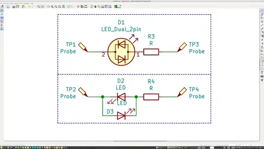
Welcome. Here is how I have been doing it for years. Use two LEDs connected parallel but in opposing directions or a two color two pin LED and resistor (300 - 500 Ohm range) in series. Connect to port pin the other end to ground or +3.3 it doesn't matter. Write some simple code to switch the pin from high to low at a slow rate like the blink program. Your Led(s) switch or change color. First test your setup by connecting 1 end to the 3.3V the other to ground and see which one lights up, then reverse the connections and the other should light. Happy testing. enter image description here

Gil
  • 925
  • 3
  • 4
0

You have not explained WHAT you connected to the Pi.

You claim to have done a number of things, but only vaguely define them. e.g "Solder a single LED and light it to see if I fried the LEDs on the previous string (didn't work)."

WHAT LED? how is connected? how did you test?

You claim to have run gpiotest (but not posted any output).
While joan's utility is worthwhile it doesn't actually test the external hardware.

I normally use my GPIOreadall for testing.
This, in conjunction with suitable programs, is a good testing tool.

You can use the inbuilt raspi-gpio to read pins raspi-gpio get 0-27 provides this in a slightly less readable form.

The following can test individual pins e.g this will set a pin as output and drive high.

raspi-gpio set 17 op
raspi-gpio set 17 dh

GPIO are not as fragile as often reported, and it is unlikely you have damaged the peripheral system, even if a couple of pins don't work.
Properly connected LEDs are a good indicator.

You can test pins with either a meter (safely connected with suitable du-pont cables) or perform loopback.

E.g. connecting GPIO17 to GPIO27 would enable you to test that you can toggle a pin and read the result.

Milliways
  • 54,718
  • 26
  • 92
  • 182
  • I did explain that I soldered a WS2812B LED earlier in my post. It was soldered with 18 gauge wire with a solid copper core. The copper core was connected to a du-pont male via my breadboard, the du-pont female is attached to pin 18 on my pi. The output said that it failed to find any faulty GPIO pins, this gives you nothing so I didn't post it. – Hopper964 Feb 23 '22 at 15:38
  • You're saying, connect GPIO17 to GPIO27 with a dupont cable, set 17 as output and drive high, then 27 as input and see if I can read 17's output? – Hopper964 Feb 23 '22 at 15:40
  • A WS2812B is NOT a LED - it a module which requires a precise timed serial input. – Milliways Feb 23 '22 at 23:56
  • So, because obviously I'm a beginner, what does that imply in the way of diagnosing my problem? Which again, is that I can no longer control it or even turn it on with my Pi's GPIO pins. Thank you. – Hopper964 Feb 24 '22 at 06:28
  • @Hopper964 the other Answer suggested using a LED to test. I explained how I test. You don't seem to have tried and still haven't said what YOU did or what you connected. You have not posted ANY results. To be clear you asked how to test the Pi - which you can't do with a WS2812. – Milliways Feb 24 '22 at 06:41
  • I hadn't tried it as I don't have any LEDs on hand. I'll get some ordered and reply with the results. Thanks. – Hopper964 Feb 24 '22 at 16:28
  • LEDs can make testing easier, but you already have the tools (multimeter) to test or use the Pi itself (as above). Using the steps I outlined above you could test ALL pins in less than an hour. – Milliways Feb 25 '22 at 01:30