10

I have a need to take photos with the Pi camera, but to illuminate the subject. The subject will be 1m or so away, but will be in total darkness most of the time. Therefore, I need a flash of some kind.

I'll only be taking a picture every hour or so. I was thinking about either:

  • A USB LED lamp (but I won't be able to turn this on/off with my Python script)
  • Some super bright LEDs linked to the GPIO pins that can be switched

Has anyone done something similar and care to share their experiences and parts list?
goldilocks
  • 56,430
  • 17
  • 109
  • 217
fistameeny
  • 201
  • 1
  • 2
  • 3
  • 3
    Does the flash need to be synchronized with the camera shutter? Or do you mean you need to switch on a light, take a photo, switch off a light? – joan May 06 '14 at 21:50
  • The latter - I don't need to synchronise, uust switch on the light, take a photo, switch off the light. That process could take a minute if it needs to, it wouldn't matter. – fistameeny May 07 '14 at 05:58
  • Just use some LEDs on the GPIOs. It is actually possible to turn 'off' a USB port: http://raspberrypi.stackexchange.com/questions/8448/disabling-usb-ports (first answer) – developius May 07 '14 at 16:36
  • Thanks for the suggestions. For simplicity, I'll get a USB LED light to prove my concept works, now I know I can switch them off. If that works OK, I'll investigate the GPIO + LED route – fistameeny May 08 '14 at 11:52
  • It better if its not synchronised as it will eliminate red eyes. But we all know how irritating it is for 3 flashes, so even flash 1 second before taking picture, then turn it off. – Piotr Kula May 08 '14 at 18:20

3 Answers3

6

I'd be tempted to go for the bright (white) LED solution. It's not something I've tried and I don't know if there will be colour balance problems.

The LEDs will likely source more than the (safe) 50 mA you can take from the Pi 3.3V rail.

I suggest you use a chip such as ULN2003A or ULN2008 to actually drive the LEDs. That way you can feed the LEDs from the 5V rail and switch them on using the Pi's gpios.

You could common up a gpio output to drive more than one ULN input. However as you don't have a pressing timing problem you might as well use a separate gpio for each LED. Using separate gpios will allow you to have coarse brightness control (by changing the number of LEDs lit).

joan
  • 67,803
  • 5
  • 67
  • 102
  • 50mA is a very conservative number. It's more like 100mA to 200mA depending on CPU/GPU/Ethernet/HDMI usage. If you are only using one pair of the ULN2003, you might as well just use a single transistor, with adequate rating of course. But most transistors can handle a few leds just fine. – Gerben May 08 '14 at 16:30
  • Have you a source for that? I thought the 3V3 rail was limited to around an extra 50 mA by the amount the 3V3 regulator could safely output. – joan May 08 '14 at 17:07
  • 50mA is the amount you get when you take the safe amount of current the regulator can output, and subtract the maximum current of the CPU, GPU, HDMI and Ethernet module. Which never occurs. Also driving the regulator a little harder for half a second shouldn't be a problem. But I'd go with the transistor and 5V solution if using more than 4 leds. – Gerben May 08 '14 at 18:39
  • 1
    I just had a quick look. I think the 50mA is the overall figure you can draw from the gpios and still maintain the proper voltage for a logic 1. Info at http://www.scribd.com/doc/101830961/GPIO-Pads-Control2 – joan May 08 '14 at 18:59
4

I'd try using several infrared LEDs, as CMOS sensors on usb webcams are also sensitive to infrared light. Depending on the size of the surface to be photographed, it could be enough with 3 or 4 of them, so it is worth to test this configuration. This setup has these advantages:

  • Directly manageable by a single transistor driven by a GPIO pin, and a resistor per led, so the circuit to build is very simple.
  • With a reduced amount of standard LEDs, you can use the same RPi power source (count some 30mA per LED if using a 330 Ω resistors, so you need some additional 120mA).
  • There is no visible light so you don't freak out people with an intermitent light. Hey, you can even have them always on, it would be a waste of energy but that circuit would be really really simple...
  • Gerben
    • 2,420
    • 13
    • 17
    Roberto
    • 358
    • 2
    • 10
    • 1
      Doesn't IR just work for monochromatic highlight though? The picture might be very faded out with IR's only. Plus you need a PIRCamera, not the standard one, if he uses that. – Piotr Kula May 08 '14 at 18:22
    • Well, you are right, all depends on what do you want the picture for. As the question talked about taking pictures in total darkness from time to time, I imagined that this was for some kind of monitoring and the chrimatic quality was not so important, related to circuitry simplicity . – Roberto May 10 '14 at 16:09
    • To be fair, the OP doesn't say if he want colour or not. He just says he need to illuminate somebody about 1m, every hour. – Piotr Kula May 10 '14 at 17:26
    • For an out-of-the-box IR LED solution the Raspberry Haiworld Version Megapixel Infrared works for me, though the color is washed out. – jlb Sep 25 '17 at 19:33
    3

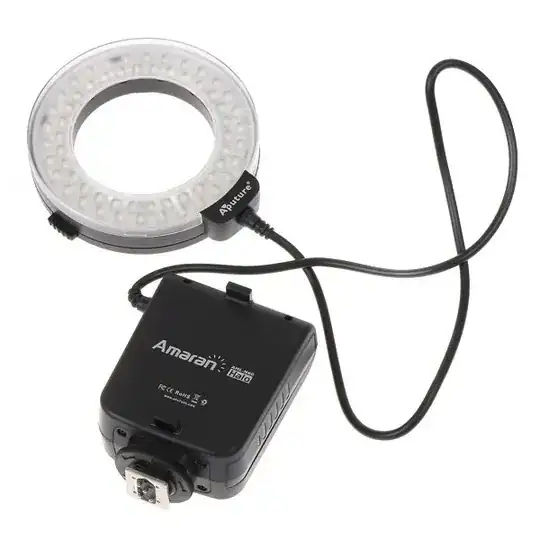
    This has its own battery pack and can be triggered by providing a voltage to the hot shoe pin (centre pin) which can be driven by GPIO connected to a transistor/ buffer/ octocoupler to be safe.

    Our friends at Electronics stack exchange can provide you with more details.

    Essentially the hot shoe has a pin that says the flash is ready- in the case of LED its always ready unless battery is dead. And the hot shoe uses some kind of mechanism to close the hot pin to GND which will turn on the light.

    Here is a fairly simple example using an octocoupler.

    Some of these LED Flash rings can provide constant light while the pin is pulled. Usefull with movie mode on most cameras.

    enter image description here

    Piotr Kula
    • 17,168
    • 6
    • 63
    • 103