121

I have seen some examples of people powering their Raspberry Pis by wiring a DC "barrel plug" style power supply to the 5V and GND GPIO pins.

What considerations should be taken when doing something like this? Do I need to add any protective components or will any decent 5V power supply with a high enough current be fine for long term use and not destroy my Raspberry Pi?

SlySven
  • 3,581
  • 1
  • 15
  • 44
BitBobBang
  • 1,211
  • 2
  • 9
  • 3
  • Do you have a picture of the power brick you want to use? or any other specifications of it? – Piotr Kula Aug 16 '12 at 10:36
  • Since ppumpkin has seen fit to ask the question on EE Stackexchange, there should be a link to that: http://electronics.stackexchange.com/questions/38077/what-is-the-implication-of-supplying-power-the-other-way-on-this-circuit – Chris Stratton Aug 16 '12 at 14:46
  • I disagree with cross posting this to EE. – Alex Chamberlain Aug 16 '12 at 18:10
  • @AlexChamberlain Agreed. That was strange behavior. ppumkin, why not encourage BitBobBang to ask EE? – Jivings Aug 17 '12 at 20:58

9 Answers9

68

By the looks of the schematic the GPIO pins are connected to +5v Rail;

I have copied part of the input schematic on the USB power. In this sub section the +5v supplied from the USB connector is filtered to give a nice stable 5v supply to the 5V0 Rail.

enter image description here

By studying the schematic you come to realise there are 3 more voltages (4 in total) used on the Pi.

  • 5.0v; HDMI (self protected)(now I know why my active HDMI to VGA works OK)
  • 3.3v; BCM and LAN IC's
  • 2.5v; DAC
  • 1.8v; BCM(RAM) and LAN

This sub circuit which is connected to the 5V0 rail has 3 voltage regulators with their own filter capacitors.

enter image description here

IMPLICATIONS

To answer your question. Yes you can supply 5v on the GPIO pin. BUT, it has no backward protection and it was not really designed to be a 5volt input pin. the 3.3v pin can also be powered with 3.3v as the regulator has build in protection- but again it leaves your BCM unprotected! Typically any power pins on GPIO area are used to power extended circuits.

You need to realise that the USB schematic was carefully designed to be used as the primary +5V input and protects the Pi from getting fried. The GPIO pin does not offer this protection fully and you really need to trust your power supply if you want to do that!

Usually people make another high powered PCB to drive other things. For example an H-Bridge used to drive motors for a robot. All it needs is TTL signals to control the motors but it runs of its own power supply; and most of the time it supplies power to the MCU/CPU via its own protective circuits isolating it from the high power circuit.

ALTERNATIVE

  1. It is not ideal but you can connect +5v to the TP1 and GND to TP2 (TP = Test Point)

  2. Cut the micro USB cable and use the RED and BLACK colour coded cables and connect it to your power adapter. Using power adapters that are rate more than 1AMP (1000ma) is fine. The Raspberry Pi will not use more than 800ma any way- But the voltage HAS to be 5votls

enter image description here

Piotr Kula
  • 17,168
  • 6
  • 63
  • 103
  • 6
    You just need to use a proper PSU. We all know the fuses cause more problems than they solve and the capacitors are still in the circuit, just not in a brilliant place - ah well, use a better PSU. – Alex Chamberlain Aug 16 '12 at 09:35
  • 1
    A lot of people are complaining about USB fuses but I havn't seen too much of them complaining about input fuse. I personally wouldn't drop fuse on input voltage and I have seen many others saying the same. One may, however, use some fuse before voltage regulator, so that it won't drop any more voltage after it is regulated but still protect from shorts. – Krzysztof Adamski Aug 16 '12 at 10:11
  • @KrzysztofAdamski Yes - Maybe they are mixing things up thinking that there is not enough power - when its just the fault of the USB IC used that will not give more power- regardless of how many amps are pumped in. There are guides on how to increase the USB fuses but cause other things to break. I strongly disagree with using the GPIO as a voltage supply – Piotr Kula Aug 16 '12 at 10:31
  • There's no reg on the 5V line; do you mean the PSU? Use a decent 1A PSU with overcurrent protection; it will shutdown properly. The input fuse is part of the problem with under voltage. As the current goes up the bad PSUs supply less voltage and the resistance of the input fuse rises, meaning the effective voltages falls further. – Alex Chamberlain Aug 16 '12 at 10:33
  • That is the problem. The OP does not specify the AMP neither the origin of the PSU or if it has any protection built in. It might work for him - but the next person will do something else and cause damage to his Pi. – Piotr Kula Aug 16 '12 at 10:35
  • 3
    Also, connecting to TP1 and TP2 is exactly the same as going through the GPIO. – Alex Chamberlain Aug 16 '12 at 10:40
  • 1
    Cant be Alex- If it was the case then the 5v bus would connect to TP1-- or the TP1 would all together be on the 5v Bus and not before the filtering caps. Does the LED light up when you connect to GPIO? – Piotr Kula Aug 16 '12 at 10:46
  • @AlexChamberlain: "decent" PSU is not really unambiguous term. If someone is using regulated PSU with overcurrent protection then it's safe. I was writing about buiding your own safty circuit for normal, not regulated PSU so voltage regulator is needed. Then overcurrent protection can be done before voltage regulator which should eliminate all fuse problems. – Krzysztof Adamski Aug 16 '12 at 10:47
  • No, it needs to be done afterwards as it is 1A at 5V... unless you do a bit of Maths of course. – Alex Chamberlain Aug 16 '12 at 10:49
  • 3
    @ppumkin The filtering caps are in parallel with the load! You can draw them anywhere you like! – Alex Chamberlain Aug 16 '12 at 10:51
  • @AlexChamberlain: Of course, you would have to use different fuse, rated for regulators input voltage, not for 5V. – Krzysztof Adamski Aug 16 '12 at 10:53
  • @KrzysztofAdamski Fair enough, just wasn't clear. The fuses in use here aren't great; they are current dependent resistors and with the SoC randomly restarting on undervoltage that isn't ideal. – Alex Chamberlain Aug 16 '12 at 10:56
  • HDMI has a diode on the +5v0 rail and it is really weird that the GPIO pins do not offer reverse current protection with diodes. I cant imagine connecting +3 to GPIO will do the Pi any good... Yes @AlexChamberlain connecting +5v on GPIO will work- But it should not be encouraged for so many reasons. – Piotr Kula Aug 16 '12 at 13:53
  • How does this information change with the Revision 2 boards? They have no polyfuse. So is there any benefit or problem with powering through GPIO instead of USB now? – Elliott B Jan 13 '14 at 03:02
  • The dangers are still the same when using GPIO with ot without polyfuse- because the polyfuse was removed somewhere else and has nothing to do with GPIO. Please check what the polyfuse removal was actually fixing - I think it was USB wattage issues? Hot plugging or something. I don't remember.You still have to be cautious if using unfused GPIO - and the USB power still uses the conventional short circuit and overcurrent fuse- which should be used on the GPIO. – Piotr Kula Jan 13 '14 at 10:33
  • 2
    Why do people make this stuff so hard? Put a 1000uF cap across the input power, then clip it with a regulator then stop it from drooping with a buck converter. That will let you take dirty power from 2.5 to 30V. If you don't like soldering there are retail boards for both adjustable regulation and buck converters. – Peter Wone Jan 10 '19 at 23:19
19

First of all, using 5V GPIO pin you are bypassing input fuse that is on the RPi. This means you have no protection in case you make some short cut etc. So if you do, a lot of current (depending on how much you power supply can supply) can flow through your Pi and can damage it. You are also bypassing TVS diode so you are basically without any protection.

Also remember that you have to put regulated 5V to this pin. Most power adapters won't output regulated voltage (unless stated otherwise on them) so you would also need to use some voltage regulator circuit.

And last thing is that there is some smoothing capacitors that makes power more stable so it would be wise to connect some capacitors yourself.

Ghanima
  • 15,578
  • 15
  • 58
  • 113
Krzysztof Adamski
  • 9,585
  • 1
  • 36
  • 53
  • 2
    The diode is also very important! +1 – Piotr Kula Aug 16 '12 at 09:38
  • 1
    That's true, of course I only meant input fuse. Output fuses are on USB only so that's not really related and of course it won't help in anyway when there is shortcut on anything other than USB. – Krzysztof Adamski Aug 16 '12 at 09:41
  • Wait, you're basically saying I could create my own voltage input circuit (with protection) and hook that up to the raspberry Pi? That's genius! I was actually looking to design a circuit, with some other connectors and transistors (to drive relays and 5v stuff! I could make that part supply aswell as output. – Paul Feb 25 '16 at 12:58
9

If you look at the schematic, you can see that the 5V pin is connected directly to the 5V rail. :)

Connecting a barrel connector to the 5V and GND pins will be fine, but be wary you won't have the protection of the input fuse - such is life. Ensure you use a properly regulated 1A@5V PSU ideally with overcurrent protection; unregulated PSUs are useless!

Alex Chamberlain
  • 15,120
  • 13
  • 63
  • 112
  • 3
    The smoothing caps are still in the circuit; they're just not in the perfect place - they'll be near the USB port, rather than the GPIO. They'll be more on the SoC anyway. With a decent PSU, I'd give it a go. With a custom expansion board incorporating a PSU, you will be more than fine - you'll probably be giving a better supply than the Pi gets atm. – Alex Chamberlain Aug 16 '12 at 09:38
  • Yes with a decent PSU - how does the OP know what a decent PSU it.. I hardly trust PSU's I use anywhere – Piotr Kula Aug 16 '12 at 09:40
  • I didn't say anything about more power. You should stick to 1A, though I doubt you'll burn out traces in reality; the chips will go first. – Alex Chamberlain Aug 16 '12 at 10:29
  • 1
    No - Image connecting a 5v 5A power source to the Pi and using the 5v rail somewhere to power motors for example @ 4AMP draw. the 5v trace will burn! Not the chip. The chip happily draws it ~500ma. If there was no fuse rated at 1A at the USB port and you supplied 5A via it- A short circuit will melt the 5V traces. That is why its there- to protect the PCB form overload and protect the CPU/GPU from over voltage(but we are not concerned about voltage here). PS I did not down vote you. – Piotr Kula Aug 16 '12 at 12:37
  • @ppumpkin this is the correct answer. The filter caps remain in the circuit. **What is important about the location of the filter caps is that they be near the load for which they provide a low-impedance reservoir.** Moving the power input does not change the layout between the caps and the load. Remember that the USB cable is much longer than any traces on the board, so the caps are unavoidably pretty far from the actual power source, and that is fine. – Chris Stratton Aug 16 '12 at 14:31
  • @ChrisStratton That is fine. As my answer shows there are 3 more voltage regulators and several more filters applied to help stabilise the relevant voltages. The +5V0 on GPIO is not fused and prone to short circuit damage. Good advice will be to avoid using GPIO as Vin ! – Piotr Kula Aug 16 '12 at 14:38
  • @ppumpkin I'm not sure you understand resetable fuses; they are best viewed in my opinion as current dependent resistors. If you short the Pi, you are still going to get large currents. – Alex Chamberlain Aug 16 '12 at 18:09
8

Yes you can. 
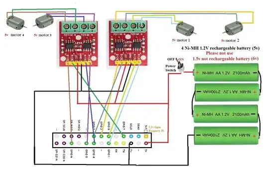
If you use battery ,and not dc power supply is very safe as in my catspberry 2 progect.

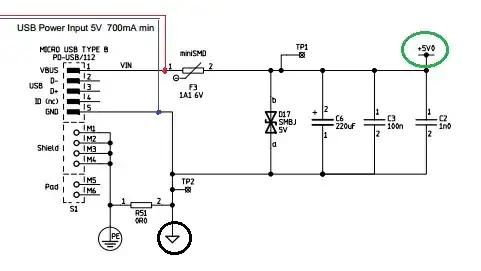
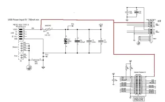
the fuse f3 protect only nvcp11117-3v3 and some resistence near hdmi.

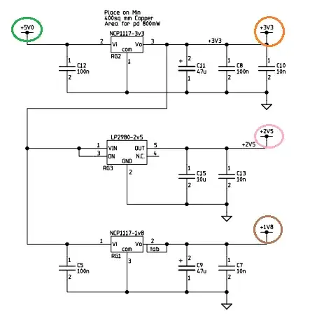
nvcp11117-3v3 Output Current Limit is typically 1A and max 1.5A and f3 fuse give max power of 1.1A.

Even if you use a dc power supply, connected to gpio, is very unlikely burn the nvcp1117-3v3 but you can use any kind of usb device.

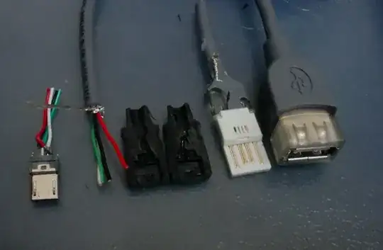
If you use microusb power connector ,to give power to raspberry pi, you can not use many usb device because there is not enough power.

A good idea was make some modification to rasperry pi to give +5v directly from "microusb power connector" to usb and gpio ,without pass through 5v+ bus,like thise .

But for now the best thing is to feed the raspberry through the gpio, because if nvcp117-3v3 burns, buying it ,on ebay, cost less then 1€ expecially if you connect noting to hdmi connector and not have risk to burn his resistences

4

Yes you can, however don't be a stupid like me, and triple chceck power connector where is + and where is -

I just burn my 3xRpi simultaniously because my imagination convinced me somehow the black cable is +....

zigfi
  • 51
  • 1
3

I designed a small board to provide power, mount an Adafruit ultimate GPS breakout and a Hall sensor input/pull up resistor. (Purpose is Open Road Racing). I used a Dimension Engineering 7805 size switching regulator and output capacitor. Works just fine and stays at exactly 4.98V. Use good parts and this should be fine.

2

You can use the 4 NiMh batteries - but I would always check that the voltage is 5v or within .25v of that. Also I used a Nokia mobile phone USB connector connected to a USB socket from a broken, cheap hub (from a pounshop originally so only £1) with only the 2 outer lines soldered to wires going to the battery pack.

z lesiak
  • 21
  • 1
  • I use your mentioned combo, 4 NiMh batts and a repurposed micro USB connector. Can run nonstop with wired network, external monitor (via HDMI) and Pi Cam for about 2 hrs or so, don't have the exact time. After the voltage gets too low, things get rather weird on the Pi. Runs a little longer without ethernet plugged in. – Chris O Aug 26 '13 at 22:49
2

Simple Fix, Soldier to the side of the fuse that goes to the USB connector to your +5v in line, and your gnd to tp2 or the side of the capacitor that goes to gnd.

Then your still using the fuse. If it is more power you need, then your left with jumping the fuse.

I'm dealing with the same issue putting an RPi on my Helicopter. Space is a concern so a modded power jack is out of the question.

Ive made a 5v 50A (drastically over powered (no heat)) regulator so i can run 12v battery instead of the 5v that is in it.

(Edit by a no-points noob: The side of the fuse that goes to the USB connector is the side towards the edge. You can tell from the layout at http://www.raspberrypi.org/final-pcb-artwork/ -- The number 1 pin goes down through a via, under the center of the fuse, and then towards the edge.)

Dave X
  • 113
  • 5
Zack
  • 21
  • 1
1

In some situations you are actually expected to power the RPi via the 26/40 Pin Header - specifically physical pins 2+4 (+5V) pin 6 + others (ground). For instance I have an RPi 1B that has been running for a couple of years now which is powered from a Basic version UPiS unit which is a UPS from PiModules, now pretty much unobtainable but replaced by the more sophisticated PICO though I suspect THAT unit now sucks in power via those same pins when the RPi is powered normally {to charge the on-board LiPo cell} and then only provides it when acting as the backup supply...

SlySven
  • 3,581
  • 1
  • 15
  • 44