2

I think of adding a RTC Module to my Raspberry Pi. I found the following tutorial.

http://www.forum-raspberrypi.de/Thread-tutorial-realtime-clock-rtc-ds1307-am-raspberry-pi-betreiben

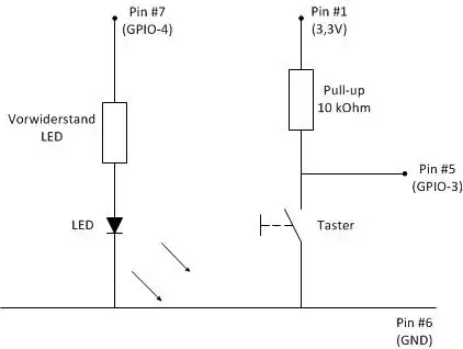
In general it's clear how I could connect it.

But I already have another thing connected to pin 5. Power Up Circuit

http://www.forum-raspberrypi.de/Thread-tutorial-hoch-und-runterfahren-mittels-taster-incl-status-led

In short words:

  • a 10k resistor between Pin#1 and Pin#5
  • a pushbutton between Pin #5 and Pin #6
  • I left out the LED on Pin #7
  • Pin #5 is configured as IN, listening for a low signal

I need to have the 10k Pullup Connected to Pin #5 and I need a pushbutton between #5 and ground. This is used to power the raspi up or initiate a shut down.


So my basic question is:

Can I connect the RTC to Pin 5 anyway or does that interfere with the wiring above?

If I cannot connect the RTC to Pin 5, is there any alternative wiring i could use?

Either connecting the RTC to an different pin, or using an alternative layout for the wiring above. One thought on that would be connecting the pushbutton to 2 pins, perhaps adding a diode if needed. And splitting the logic a bit.

Shortcircuit between #5 and ground for power up (there is no alternative) and listening for low on any other free pin for shutting down.

Thanks in advance :)

Ghanima
  • 15,578
  • 15
  • 58
  • 113
Christoph Daum
  • 165
  • 2
  • 8

4 Answers4

2

The RTC uses pin 5 as an output, for the SCL signal. But you want to use it as an input. This could be difficult, and could even damage the Pi (if SCL is 3.3V and you press the button you'll be creating a short, possibly damaging pin 5 and maybe even the entire chip).

To prevent any damage you could add a resistor between pin 5 and the button.

Reading pin 5 while it is an output isn't possible, but you can just connect a second (free) pin the the button, and read that one. See schematic below

This doesn't work

The top resistor should be less than 116Ohms to make GPIO 5 get below 0.8V. This is because of the relatively low value (1.8K) pull-up resistor present on the board, and the voltage drop of the diode. However when pin 5 is an output, and high, 28mA will flow when the button is pressed. Which is more than the Pi can handle.

To prevent a LOW on output-pin 5 from registering as a button press you need an additional diode.

Not ideal, but it will make you use a single button for both wake-from-halt and shutdown. Also note that it will disrupt I2C communication if you press the button while the PI is talking to the RTC module. Though the chances of that happening are slim, as communication is maybe once every few minutes, and only takes a few milli-seconds.

Gerben
  • 2,420
  • 13
  • 17
  • You can read gpios which are set as outputs. The current level is returned (which may not be the commanded level). – joan Jun 25 '14 at 20:05
  • 1
    Thanks. That's what I wanted to know. For now I will not follow this thought though. After a deeper thought I don't see any advantage to my project. Btw which programm did you use for creating the diagram. – Christoph Daum Jun 25 '14 at 21:06
  • @Gerben I don't see what the circuit above is supposed to achieve. Pressing the button will pull pin5 to ~1.7V, which even if configured as an input will not be reliably detected as low. As another pin is being used to detect button push it also seems to achieve nothing. – Milliways Jun 26 '14 at 01:20
  • I forgot about the 1.8k pull-up. The 1k resistor should indeed be a bit lower to work properly. What the circuit does? when the pi is shut down, pulling pin 5 low will make it boot up again. – Gerben Jun 26 '14 at 07:44
  • Circuit was created in KiCad. Free and open source software. – Gerben Jun 26 '14 at 07:45
1

The RTC seems to use the I2C interface which requires the secondary functions on pins 3,5. (You could use the I2C on P5, but this would obviously require modifying the RTC software.)

There seems to be no reason why you could not use any of the other GPIO pins for the existing functions, although this would require minor changes to the software.

Incidentally there is no need for the 10KΩ pullup in your existing circuit as pins 3,5 already have 1.8KΩ pullups.

Milliways
  • 54,718
  • 26
  • 92
  • 182
  • As far as I understood the example, I need the pullup between 1 and 5 to get a clear high on #5, as it listens for a low to initiate the shutdown. I don't see how I get this to work without the pullup. As mentioned above I definately need pin 5 for the power up feature. I could for sure use another pin for the shut down feature, as long as there is a wiring that makes it possible to use the same button for features without interfering. – Christoph Daum Jun 25 '14 at 13:37
  • The pi's [wake-from-halt](http://raspberrypi.stackexchange.com/questions/13203/creating-halt-wake-button) function is also attached to pin 5. – Gerben Jun 25 '14 at 18:02
  • @Gerben I see nothing in the referenced post which indicates anything special about pin 5 (other than the on-board pullup). Any other pin could be used. The P6 header can be used as wake-from-halt. – Milliways Jun 26 '14 at 01:16
  • @ChristophDaum pin 5 (and pin 3) have 1.8KΩ pullup resistors on board (to facilitate I2C use). Adding another 10KΩ won't hurt, but is not necessary. – Milliways Jun 26 '14 at 01:25
  • @milliways see here http://www.forum-raspberrypi.de/Thread-tutorial-hoch-und-runterfahren-mittels-taster-incl-status-led paragraph IV. It says for powering up connect pin 5 to ground. – Christoph Daum Jun 26 '14 at 04:57
  • @ChristophDaum I don't read German, but pin 5 is used ONLY because the software uses this. You could use any other pin and not interfere with the I2C interface. – Milliways Jun 26 '14 at 05:07
  • If you can change that via software. Share the knowledge. Otherwise that hint is quite useless. – Christoph Daum Jun 26 '14 at 05:09
  • @ChristophDaum I assume you are running the script which starts `# shutdown script for Raspberry Pi # watch LOW level on pin 5 to enter sleep mode # status led on pin 7: ON = ready, BLINK = confirm button` Just change the 5 to some other GPIO pin. Incidentally it is poor coding practice to hard-code pin values. You should use a symbolic constant. – Milliways Jun 26 '14 at 05:12
  • That's the script for shutting down, that's clear to me that and how I could change that. We are talking about the ability of pin 5 as a power up button when rasp pi sit shut down. Unless there is something I don't know, no piece of software runs while raspi is on halt. – Christoph Daum Jun 26 '14 at 05:15
1

I was facing the same problem; I had i2c RTCs, many models, and found that I needed to wake from halt, which was a problem. The solution was to switch my choice of the RTC over to an SPI based one. The one I ended up using was the DS3234.

Key Features

  • Highly Accurate RTC with Integrated Crystal and SRAM Completely Manages All Timekeeping Functions
  • Accuracy ±2ppm from 0°C to +40°C
  • Accuracy ±3.5ppm from -40°C to +85°C
  • Real-Time Clock Counts Seconds, Minutes, Hours, Day, Date, Month, and Year, with Leap Year Compensation Valid Up to 2099
  • Digital Temp Sensor Output: ±3°C Accuracy
  • Register for Aging Trim
  • Active-Low RST Input/Output
  • Two Time-of-Day Alarms
  • Programmable Square-Wave Output
  • Simple Serial Interface Connects to Most Microcontrollers
  • 4MHz SPI Bus Supports Modes 1 and 3
  • Battery-Backup Input for Continuous Timekeeping
  • Low Power Operation Extends Battery Backup Run Time
  • Operating Temperature Ranges: Commercial: 0°C to +70°C, Industrial: -40°C to +85°C
  • 300-Mil, 20-Pin SO Package
  • Underwriters Laboratories® (UL) Recognized

The temp sensor was a bonus, as I could use that for alerting of the ambient temperature of the RPI

Clown Man
  • 131
  • 1
0

Sorry. As far as I'm aware pins 3 and 5 are used for the hadware I2C port of the raspberry. There is another port available but it's used for HAT connectivity. I'd advice using another GPIO port for your input.

This website (not mine!) shows the different capabilities of the raspberry's GPIO header: http://pinout.xyz/

DrBomb
  • 86
  • 2