Let's have a high-level overview of what an oscilloscope has:
First we have the analog front-end. Here we have impedance-matching network for the probes (but the probes will have to have a capacitance matching part too), attenuation section (very important, so we don't overload the ADC or let high voltages in), triggering and connection to analog to digital converter. I won't talk too much about this, since I'm not too good with analog stuff, but the bottom line is: There's nothing we can do with Pi in this section.
Next we have the analog to digital converter part. You'll need at least one ADC for each channel. More can be used for higher sample rate. In traditional scope, the ADC is connected to an ASIC or a FPGA device. They are used because traditional computers aren't real-time enough (and don't confuse real-time with fast!) to process the data provided by the ADC. That data is then stored into RAM of some sort. Some devices will use static RAM, wile some other will use dynamic RAM. In general the SRAM approach is more traditional and seen in big-name manufacturers, while DRAM use seems to be the newer approach seen in the cheaper Chinese-designed units.
The amount of RAM and its speed will determine how many samples can be stored. Almost always the ADC will be 8-bit ADC, so for say one megasample we'll need 8 b times 100000 = 8 Mb or 1 MB of RAM. For one MSa/s, we'll need RAM which can work at that speeds. Today, that should be relatively easy to obtain. The FPGA usually drives the RAM directly and is responsible for storing data in it. It works by filling the sample memory while there's still empty room and then overwriting it when it's full. When there are multiple ADCs per channel, the FPGA will set them so that first starts sampling, then on the next clock second and so on. When they finish sampling, sample of the first ADC will be written into memory first, then second ADC's sample. This will make it look like the ADCs are sampling faster then they really are.
Next point in this section is that the samples should be equidistant in time. This is the main problem with use of PCs in oscilloscopes and the reason why FPGAs and ASICs are predominant. If some samples are late or early, then the image represented on screen will be incorrect.
In this part we see the first possible use of the Pi. If the sample rate is low enough, we might be able to drive the ADCs directly from the Pi and store their results in Pi's RAM. How fast we can go depends on the way the ADC is connected to the Pi and how Pi does its I/O. From what I've read, the highest speed of Pi's I^2C ports is 150 MHz (how easy that would be to achieve in GNU/Linux is another question) while the highest standardized speed is 5 MHz and for SPI the highest speed in Pi is 250 MHz. I'm not sure what is the highest standard speed of SPI, but I expect it to be somewhere in the 100 MHz range at the maximum.
So in theory we have more than enough speed on Pi to run an ADC in low MSa/s range. I have a feeling that the RAM speed won't be a problem here, but I don't have any data to back that up. If that is the case, then we'd have a major benefit over usual scopes: There would be very large amount of capture memory available. For example if we dedicate 32 MiB of RAM to the program for sample memory and we have two channels, that would leave us with 16 MiB for each channel or a bit more than 134 Mb or 134 megasamples per channel. That's something that even today many oscilloscopes don't have.
The downside is that we'd need heavy modifications to the operating system in order to be able to get accurate sampling here. I don't have any experience with real-time Linux, so I don' know how easy this would be.
Anyway, let's get to the next step. So we have a sampling system that's filling up the RAM. Next part is the trigger. Trigger is closely related to the screen refresh rate. What it basically does is finding an interesting sample and holding it in memory. When the scope triggers, it continues sampling after trigger until it has filled up the memory and then it sends it to be processed and displayed on screen. While the data is being processed, sampling system if often frozen and waiting for the data to be displayed. That is why low-end scopes have lower refresh rates while high-end scopes will have special high refresh rate displays and spend much less time waiting for the data to be displayed.
In this section there will often be another ASIC or FPGA that will do signal processing on the samples, any protocol decoding if the scope supports it and actually driving the display itself.
This is the part where from what I can see the Pi can really shine. It can drive a nice 1920x1080 display (while scopes are often in the sub 800x600 land) and can do protocol decoding very nicely. The only problem I can see would be speed and how processing would affect the hold-off time. If we go for a low refresh rate, then we can get a really good logic analyzer with it.
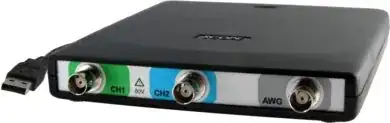
Finally a word about USB oscilloscopes and why USB is bad in general for this type of project: Traditional USB oscilloscope does input and sampling and sends the sampling data over to the PC for processing for which a host application exists. Basically something very similar would be done with Pi too. Usually the PC applications are badly designed and full of bugs. Next bad part is USB itself. It's advertized as fast bus which can do 480 Mb/s in "Hi-Speed" mode. The truth is that it's extremely rare to find a USB controller that can support such high speeds (the average seems to be around 250 Mb/s from what I've seen) and that it as a protocol isn't very suited for any real-time application. First it's shared among all devices on a hub (and Pi only has one USB port to which Ethernet+USB Hub is connected), has relatively high overhead (when compared to say SPI) and has high latency (remember that at 1 MSa/s each sample lasts for just 1 µs, so we must have memory on our board since we can't send samples in real-time over USB). Finally using USB would make the data acquisition part o the scope to be just another USB oscilloscope and that's where we loose any benefit of using Pi: Traditional desktop computers are much more common, faster, more easily obtained and have much better USB capabilities.
EDIT
I've read a relatively recent post by Gert van Loo and according to him, realistic rates for Pi's I^2C are 400 kHz and for SPI are 20 MHz.