29

I want to use my Pi as an XBMC server in the car. The XBMC docs say that you should always use the shutdown command before disconnecting the power.

I've been thinking that it should be possible to create a simple circuit with a capacitor and probably a diode to detect when the power supply was disconnected (and raise an interrupt on one of the GPIO pins) but the capacitor would provide current long enough for the system to shut down properly.
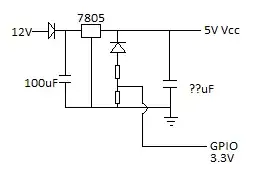
first draft

Does this look correct and sufficient?

...Actually, I think it would probably be more like this:
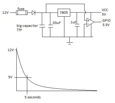
second draft

What kind of capacitor would I need to store enough charge to keep the Pi going long enough for XBMC to shut down properly?


For the record, this question was also asked on SE Electrical Engineering.

Nicholas Albion
  • 409
  • 1
  • 4
  • 5
  • What is with the "GPIO 3.3V"? In the first circuit it will just pull down the 3.3V rail with the bottom resistor, and the second connecting the output of an Op-amp running from 5v single-ended supply to GPIO with the inputs as set will have the op-amp driving its output close to 5V as hard as it can - which is not going to help the 3.3V supply to the Pi (**it may kill the Pi**). The use of a Linear Power regulator (7805) is just going to waste the limited charge in the ?? capacitor. I would "-1" this but the question is good even if your suggestions are poor. – SlySven Dec 20 '15 at 19:31
  • I dont think any kind of capacitor will do as it may take up to 30 seconds to shut down a Pi. You may need to look at a tiny UPS system instead. Or you cant try this, but its a 90USD project. http://www.instructables.com/id/The-Forever-Rechargeable-VARIABLE-Super-Capacitor-/ – Piotr Kula Dec 20 '15 at 21:03

5 Answers5

13

Projects to add shutdown and startup functionality to Pi:

There is also a solution to switch Pi on/off but it does not cut the power so it is not suited for a car:

avra
  • 1,243
  • 7
  • 9
4

The best solution on my opinion is to use the UPS Pico , a specially designed for Raspberry Pi UPS, that offer a plenty of other features.

It is low cost, includes battery, no need for any extra cable, just put it on top of RPi.

Running on a car, and automatic shutdown, also running on XBMC.

Ghanima
  • 15,578
  • 15
  • 58
  • 113
Alexander
  • 71
  • 1
3

Comparator's output goes to GPIO pin (in this circuit there is placed multimeter instead) so that Raspberry could check if car's ignition is still on. Everything else is explained by the previous speaker. "S2" is a reset buttun - just in case. In the picture you can see XMH4, XMM1,.. Don't care about it. I've used it only to check interesting parameters while testing circuit in Multisim. My only question is reaction to rising temperature. Perhaps, there will be need to change the values of resistors in voltage dividers.

Edit: I've realised that in spite of the fact that the cirucit is surely correct in the theory, it is useless. Cost of such a big capacitor (1F, 12V) is unacceptabe high. Another solution might be connecting voltage regulatior stright to acculumator and using voltage comparator between car's ignition and the battery.

enter image description here

swojczak
  • 31
  • 3
  • 4
    Hello and welcome! Thank you for your contribution. Care to explain the workings of your circuit? – Ghanima Dec 09 '14 at 16:36
1

It may be possible to design a suitable circuit with a set of "super-capacitors" batteryuniversity.com article & Wikipedia entry and something like what you get from an on-line auction site if your search for a "3V to 5V 1A DC-DC Boost Converter" - you would another (say 5-25V in to 5V 2A(?) output Buck-Boost") converter to drop the 12V (well 13.8V) Car Supply to the 3 to 5 Volts needed to keep the capacitors charged - then the first converter uses that to power the Pi.

You'd want to monitor the incoming 12V to detect it being switched off and to tell the Pi to shut-down (like the UPiS devices in the other answer does!)

You would also need some inrush prevention in the circuit as the super-caps will take a large surge current (from the 12V converter) when voltage is applied to them and they are discharged.

For the record: individual super-caps usually have a maximum voltage of less than 5V but you can now buy units that have two in-series to operate with 5V volts - however it is not a good ideal to put more than 2 or 3 in series without extra "voltage-balancing" circuitry which just make the design more complex - the reason to use a "boost" converter is that it will keep producing 5V when the voltage from the capacitors drops below that...

SlySven
  • 3,581
  • 1
  • 15
  • 44
1

Keep it simple and prove your project is worth the effort of a UPS.

Just add a momentary switch to short a couple of GPIOs that triggers a shutdown. The Pi will power up when the car is started next time. Be wary your supply is only delivered after the engine has started, to prevent a dip during the ignition process.

Create a script:

$ nano shutdown.py

Enter the text;

import RPi.GPIO as GPIO
import os
channel=11
GPIO.setmode(GPIO.BOARD)
#Pin 11 & Gnd
GPIO.setup(channel, GPIO.IN, pull_up_down=GPIO.PUD_UP)
GPIO.wait_for_edge(channel,GPIO.FALLING)
os.system("sudo shutdown -h now")

Add the line below to /etc/rc.local

Python /home/pi/shutdown.py

Connect a wire to pin 11 and a wire to a Gnd pin.

I'm not sure how well Kodi plays with GPIO switches so it may have to be within Raspbian.

Andy Anderson
  • 608
  • 4
  • 11