1

There are loads of Youtube videos on how to control a relay, but I simply want to be able to power up my Pi and let it activate a relay. Then, when I power it down, it should turn the relay off.

No buttons or interfaces, just on and off.

I've built a arcade machine and have illuminated buttons. But I want them to turn on when I power on the pi and off when I'm finished. I have bought the relay as I have LED strips lighting also and just waiting for it to arrive. Do I need code or can I just simply attach to the GPIO 5v and ground?

I'm not sure if just plugging it in and hope for the best is a good idea. It's only £30 to replace, but it's still £30 quid. Grrr!!

Hopefully someone can help .

Kind regards brent

PS. As you can tell I'm not a programmer. I like the idea, but I just need to get this problem sorted first. Then I can mess with the next Pi I buy.

Starting to get the bug...
MadMike
  • 583
  • 4
  • 19
  • Welcome to raspberrypi and posting a good question. I would be nice if you would [edit](https://raspberrypi.stackexchange.com/posts/71392/edit) your post and mention what OS you've installed. It would also be nice if you would link the mentioned Youtube videos. – MadMike Aug 19 '17 at 14:49
  • Just remember to protect the Raspberry Pi GPIO with a "flyck back" diode. Inductive load can destroy your GPIO ports. And normally the Raspberry Pi can't drive a relay, it needs a transistor circuit. example: https://i.stack.imgur.com/4qyrw.png – MatsK Aug 19 '17 at 21:01

3 Answers3

2

I have made the same to control a relay and switch on/off my 3D Printer from my computer. I assume you are running the latest rasbian. You need to run a python script like that:

import RPi.GPIO as GPIO
GPIO.setmode(GPIO.BOARD)
GPIO.setup(12,GPIO.OUT)
GPIO.output(12,1)

Make a file (relay.py for example) and copy paste the above script, save and exit. That script will use PIN 12 and will set it HIGH so you can turn on your relay.You run the script with command "python relay.py" You need also to make it autostart on boot.

Your relay need of course to be driven with a NPN transistor. Be sure to connect your leds on the NO (Normaly Open) pin of the relay. That way when you turn off raspi the GPIO will be off and relay in NC (Normaly Closed) contact so leds will turn off. I dont know your experience but look here for some more information https://learn.sparkfun.com/tutorials/raspberry-gpio/python-rpigpio-api

Good luck and always double check connections before you power on!

  • Using Rpi GPIO output mode 3V3 signal to drive an NPN transistor such as 2N2222 which in turn drives a bare RELAY SWITCH such as 5V Songle relay switch is a bit risky. I think a safer solution is to use a cheap 5V RELAY MODULE (recommend High level (NOT Low trigger) trigger type, from Amazon, AliExpress etc). – tlfong01 Sep 08 '19 at 09:41
  • Relay Switch vs Relay Module: https://imgur.com/gallery/VNGSttK – tlfong01 Sep 08 '19 at 09:50
  • Relay Module Selection Suggestion: https://raspberrypi.stackexchange.com/questions/99988/how-to-wire-a-raspberry-pi-to-a-16-channel-relay-module-it-wont-work – tlfong01 Sep 08 '19 at 09:54
1

Here's one of many solutions to this problem. It relies on you properly shutting down your Pi by running something like sudo shutdown or clicking a shutdown button on your OS. If you use sudo halt or sudo shutdown -h or simply unplug your Pi, this will not turn the relay off.

Turning the Relay On at Boot

You will need a script that turns the relay on. Most likely this will be a Python script that looks something like:

#!/usr/bin/env python3
import RPi.GPIO as GPIO
GPIO.setmode(GPIO.BOARD)
GPIO.setup(12,GPIO.OUT)
GPIO.output(12,1)

Notice the #!/usr/bin/env python3 (known as a shebang). This is important as it tells Linux that this is a Python script, specifically Python 3 (you can replace python3 with python if you are planning on using Python 2.x. Save this "relay on" script (which will not look identitical to what I have posted above) as relayOn with no extension necessary.

Move this file to /etc/init.d/. This is the directory where scripts are ran during boot. You will also need to make this script executable by running chmod +x relayOn.

Turning the Relay Off at Shutdown

Similar to /etc/init.d/ there is a directory in which scripts are executed during a shutdown. This is /etc/rc6.d/. So, to shut down your relay when your Pi shuts down, write a similar Python script (don't forget the shebang) that turns the relay off. Save it as relayOff (again no extension required) and move it to /etc/rc6.d/. Again, make this script executable with chmod +x relayOff. Now this script will execute during a proper shutdown.

Patrick Cook
  • 6,245
  • 5
  • 35
  • 61
1

Do I need code or can I just simply attach to the GPIO 5v and ground?

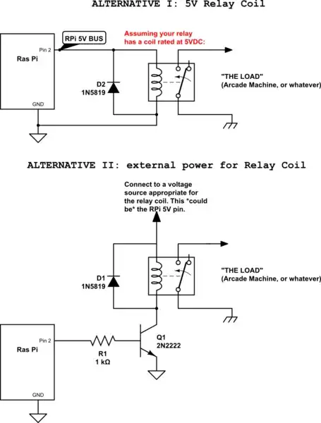
Yes, you are spot on. No code is needed, and no "GPIO" pins needed. Note that the 5V bus is not a GPIO per se - 5V is available on pins 2 and 4 of the 40-pin header as shown here.

Assuming your relay has a coil that is rated for 5V simply connect the relay coil as shown in ALTERNATIVE I below. Here's how it works:

  1. When you power up your RPi, the 5V bus will be enabled. The 5V bus (pin 2 on the header) will in turn energize the relay coil, moving the contactor from the open terminal to the terminal connected to your "arcade". If wired correctly, this will turn on your arcade.

  2. D1 is necessary to protect the RPi from the inductive "kick" when the magnetic field in the coil collapses at turn-off time. D1 must be a Schottky diode. See also

If your relay coil is rated at more than 5VDC, the circuit at ALTERNATIVE II must be used.

  1. Q1 and R1 are necessary to "buffer" the RPi from the higher voltage, and switch current through the coil to operate the contacts. In this case, when the 5V bus comes up, it causes a small current to flow through R1 into the base of the transistor Q1. This in turn biases Q1 such that current may now flow unimpeded through the coil and Q1's C-E junction.

  2. Note that your "LOAD" (the arcade) need not be connected to the same ground that your RPi uses. In fact, the "LOAD" need not be DC at all - it could be an AC voltage. The coil and the contacts are said to be "galvanically isolated".

Here's how to wire this arrangement:

schematic

simulate this circuit – Schematic created using CircuitLab

Seamus
  • 18,728
  • 2
  • 27
  • 57