0

I have a working DIY UPS for my Raspberry PI 3B board. My requirement is that whenever the main power goes off the PI, the software should be able to detect it and immediately trigger a graceful shutdown. Right out my plan is to poll regularly the DC adapter (5V / 2A output) positive line by connecting it to a GPIO pin. With this, I need your help on:

  1. Knowing the voltage/current tolerance of GPIO pins.
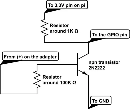
  2. Any additional component(s) need to be added before connecting to GPIO pin.
  3. Deciding a proper GPIO pin (with number) for my requirement.

Thank you for your time and help.

moosambi2020
  • 121
  • 4

5 Answers5

2

All the Pi's GPIO are 3V3.

You at least need a resistor divider between the 5V and the Pi GPIO you choose to use. Ensure that the resistors chosen will drop the maximum voltage generated by your power supply (likely more than 5V) to a Pi safe 3V3.

You can use any GPIO you want.

https://pinout.xyz/

joan
  • 67,803
  • 5
  • 67
  • 102
1

You could use a npn transistor and resistor, like this:

schematic

simulate this circuit – Schematic created using CircuitLab

Ths would work like this: the positive output from the adapter(which flows through the resistor, which reduces the current) keeps the transistor switched on, which supplies ground(negative voltage) to the GPIO pin. Then, when the power disconnects, the transistor switches off and the 1K pullup resistor takes over and supplies 3.3V to the GPIO pin, which activates the shutdown.

I have never tried this(I came up with it just now), but I think it would work. If you have worked with transistors before, this should be pretty easy to implement, if you haven't, it would be a little harder. If you decide to try this, let me know if it works, and I hope this helps you!

Benjamin Ashbaugh
  • 1,059
  • 6
  • 17
1

enter image description here

This is the schematic of the UPS circuit. As I mentioned in my question, my plan is to monitor the 5V positive line (Pin 2 - Barrel Connector), this is where the DC adapter will be connected. It would be great if anybody can suggest much simpler and safer way to monitor the presence of 5V input. Do let me know if you need further information.

moosambi2020
  • 121
  • 4
0

The GPIO pins of Pi aren't built to take 5v.

You could use a voltage divider (two resisters which will divide the voltage so that you have 3v3 to deal with). This is a simple solution, but has some problems also. For instance, a simple voltage divider won't protect the gpio pin from voltage spikes from your power supply.

In my opinion, a slightly better solution would be to use an lDO (low dropout) voltage regulator. A quick search turned up the Microchip MIC5365-3.3YC5-TR which is only about $0.15 at a single-quantity price. You could not power a Pi off of this chip because it only runs about 150 mA.

You'd still want to put a series resister along with it to keep the current down.

I assume that you'll also have enough battery power in your UPS to keep the Pi awake long enough to shutdown properly.

As for your other questions, simple research, both here, and at raspberrypi.org will answer them. I believe that any unused GPIO pin can be used for your project.

NomadMaker
  • 1,542
  • 6
  • 10
  • Yes, the battery has enough juice for the PI to allow for a graceful shutdown. The PI is always powered from the Vout pins of the UPS module with regulated 5V output. The DC adapter input is connected to the UPS Vin pins. Also, the regulator output current is mentioned as 150mA. Should I be concerned with that? I hope that much current will not kill the GPIO or SoC. Please let me know thoughts. – moosambi2020 May 16 '18 at 13:15
  • This is why I suggested a resister in series with the regulator. Just like any current source, you don't want it to overload your Pi. – NomadMaker May 16 '18 at 21:42
0

There are probably other issues in reliably detecting loss of power in your circuitry which you will have to address, but if your question is detecting an external 5V level you should use a voltage divider.

  1. The voltage divider should be of relatively low impedance (< 500Ω) to minimise sensitivity to interference.
  2. To ensure protection from transients and over-voltage to should use a diode clamp (basically a diode from the centre point of the voltage divider to Pi 3.3V).
  3. The voltage divider should aim to provide ~2.2V to the GPIO (trigger point is ~1.3V).
  4. You can use ANY GPIO, but avoid those used for I²C (pins 3,5) which have pullup resistors.

See Electrical Specifications of GPIO

NOTE Comments about limiting current are wrong! The GPIO are high impedance, and will draw no current, but to protect against damage caused by setting GPIO to output you should use a series resistor from voltage divider to GPIO. This should be ~1kΩ; this is normally unnecessary with a voltage divider, but is a good idea for a low impedance circuit, and certainly does no harm.

Milliways
  • 54,718
  • 26
  • 92
  • 182