2

I'm trying to connect a Joystick/Encoder/Button (Copal Electronics CJ25) to a Raspberry PI. Using gpiotest I managed to get it up and running pretty well - using 3.3V input (though the data sheet mentions 5V).

The problem is, that each of the joystick's axes has 3 levels of voltage as output. 0x, 0.5x and 1x input voltage. So with 3.3V input there's 0V, ~1.7V, 3.3V.

Is there a way to simply step up/down voltage (resistors?), so that by using two different GPIOs I can detect all three states with those digital I/Os ?
ftw
  • 33
  • 5
  • 1
    Ah, the joystick's tristate logic of 0V, 1.7V, 3.3V is interesting. I immediately think of using an ADC, eg MCP3208 to convert to 2 bit values, 00, 01, 10. Of course for Arduino with ADC pins, we don't need any external ADC. For Rpi, Low level max is about 0.8V, so 1.7V and 3.3V are above 0.8V will be read as High. Your two different pins way looks good. So if we step down the input to 1/3, then one pin can tell 0V and 1.7V/3 = 0.6V as low. The other pin can tell the non stepped down 1.7V and 3.3V as high. In other words, if one pin says high, the other pin says low. Then it middle. – tlfong01 Jun 21 '19 at 09:11
  • Thanks! l'd really like to avoid any additional ADC, but by using two GPIOs I'ld need to know what resistor values to use, and that depends not only on voltage but on current, right? As I understand the max overall current is 50mA for all GPIOs. Maybe someone had a hint on how to *safely* connect that single input to two GPIOs stepping down the voltage by resistors on the 2nd GPIO? Thanks in advance!! – ftw Jun 21 '19 at 09:45
  • The Pi is pretty irrelevant to this question. – joan Jun 21 '19 at 12:34
  • 1
    I agree two GPIO pins is better than an external ADC. I said I immediately thought about ADC because I have been using ADC too often. I must admire your two input pins to differentiate 3 logic level is innovative and I have never thought of that. Coming back to the voltage divider using resistors, a very simple rule of thumb is to limit GPIO current to 2mA. So take 3V3 as maximum, a safe total resistor value is 3V3/ 2mA ~= 3k/2 ~= 1.5k. To add a little bit safe margin, I would use total resistance ~= 4k7 to 10K. My calculation is dodgy, not proofread. :) – tlfong01 Jun 21 '19 at 12:38
  • @ftw, I read about tri state logic but never seen a real device using tri state logic. So I was curious to read the datasheet to see the spec. But I was surprised not to find and logic table showing three states as you said 0x, 0.5x and 1x. Can you confirm if you are really using CJ25, and let me know which logic table shows three states. As I can see the "A" and "B" outputs are only two states. – tlfong01 Jun 21 '19 at 14:38
  • @joan The Pi is not that irrelevant to this question as I'm asking for a PI-safe way of using it's 3.3V GPIOs with this encoder/joystick. – ftw Jun 21 '19 at 15:56
  • @tlfing01: The tristate is described on the 2nd page of the data sheet at "Joystick"->"Output signal". It states 0, 2.5 and 5 volts, but I tested it with 3.3V and got the equivalents, so the "neutral" state results in half input voltage. I'll give the resistors solutions a try, thanks! – ftw Jun 21 '19 at 15:58
  • @tlfong01 ... left side of last page ... joystick diagram ... center position is 2.5V – jsotola Jun 21 '19 at 17:00
  • @ftw, you could use two comparators to detect the position of one joystick axis ... use something like a 555 timer as a voltage comparator ( or use a 556 dual timer ) ... set one to trigger at 1V ... the other at 2V ... the two outputs would be read as 2 bits of data – jsotola Jun 21 '19 at 17:07
  • @jsotola, Oh my goodness, how could I miss that. I thought hard and have concluded two reasons: (1) Old dog cannot learn new tricks, (2) my eye/brain communication/control/analysis (neural network pattern recognition etc ) is a very little bit weaker/peculiar from average/normal (I knew this when I was 14. More about this later). – tlfong01 Jun 22 '19 at 01:12
  • Now the old dog is learning new tricks. It starts with the following: (1) JoyStick - Wikipedia https://en.wikipedia.org/wiki/Joystick (2) Getting started with the Sense HAT Joystick https://projects.raspberrypi.org/en/projects/getting-started-with-the-sense-hat/10 (3) SenseHat python roll [on hold] https://raspberrypi.stackexchange.com/questions/99763/sensehat-python-roll/99766#99766 – tlfong01 Jun 22 '19 at 01:46
  • @jsotola, OMG, old dog cannot learn new tricks agn. Have been using 555 many years, always multi frequency band, adj freq osc sig gen. I know 555 can do monostable. So I only know how to use 555 as bistable or monostable, but never as a comparator. I vaguely remember RS/JK/D flip flop principles. But I forgot if bistable means oscillator. So the old dog even forget old tricks! :( I embarrassingly admit I was once a Fairchild engineer, testing ICs 555/556/709/741/723/78xx/79xx, cannot remember more names, but mostly noble, shiny, bright, metal cans, not ugly look cheap black plastics. – tlfong01 Jun 24 '19 at 03:26
  • @jsotola, just now I googled to find how can 555 be used as a comparator. I found comparator is a common use, most newbies should know about it, for a very special reason: the 555 comparator cct uses 5k, 5k, 5k, therefore the name 555. OMG, I actually signed off perhaps millions of 555s in my Fairchild QA enggr days, but until now, I never knew why it is called 555. This indeed damages my reputation, losing big face! :) https://www.quora.com/In-IC-555-do-we-have-a-comparator-or-a-logic-gate – tlfong01 Jun 24 '19 at 03:43
  • @jsotola, you remind me that many years ago, when I worked in Fairchild, I was very excited to know about the toy 555, and wish to tell everybody this interesting toy. So I joined a charity organization's free basic electronics interesting group, as a voluntary instructor, teaching ohms law, resistors, and capacitors, and most importantly 555! https://www.raspberrypi.org/forums/viewtopic.php?f=63&t=2316&p=1415535&hilit=fpga#p1415535 – tlfong01 Jun 24 '19 at 03:54
  • @jsotola, you might like to check out my profile in EE stackExchange https://electronics.stackexchange.com/users/187471/tlfong01?tab=profile I was not exaggerating when I said I signed off millions of tested NE555, 2N2222 etc. In those days US enggr designed ICs, but a huge proportion of the ICs were assembled and tested in my city, with smart but very cheap labour. https://en.wikipedia.org/wiki/555_timer_IC As of 2003, 1 billion units were manufactured every year, . most popular IC ever manufactured. - Wiki. And because of mass production, so 555 is dirt cheap these days, ... – tlfong01 Jun 24 '19 at 04:15

2 Answers2

2

You MAY be able to use the Pi logic levels to detect this, but it would be unreliable. (The trigger point is ~1.3V, but varies from Pi to Pi.)

The only thing you can rely on in <0.8V => LOW; >2.0V => HIGH.

See Electrical Specifications of GPIO and https://www.raspberrypi.org/documentation/hardware/raspberrypi/gpio/README.md

An ADC would be overkill, all you need are voltage comparators - these are cheap, and available in multi comparator packages e.g. LM339 or LM393. See https://en.wikipedia.org/wiki/Comparator

Milliways
  • 54,718
  • 26
  • 92
  • 182
1

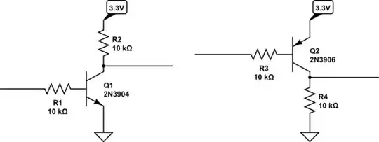
Attach level shifters with different thresholds on two GPIO pins to distinguish more than two states:

schematic

simulate this circuit – Schematic created using CircuitLab

Q1 will output 3.3V only when the input is below 0.6..0.8V, otherwise it will output 0.3V or less

Q2 will output output 0V only when the input is above 2.5..2.7V, otherwise it will output 3.3V.

Dmitry Grigoryev
  • 26,688
  • 4
  • 44
  • 133