Armature (electrical)
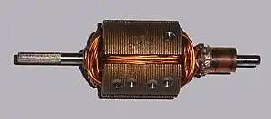
In electrical engineering, the armature is the winding (or set of windings) of an electric machine which carries alternating current.[1] The armature windings conduct AC even on DC machines, due to the commutator action (which periodically reverses current direction) or due to electronic commutation, as in brushless DC motors. The armature can be on either the rotor (rotating part) or the stator (stationary part), depending on the type of electric machine.


The armature windings interact with the magnetic field (magnetic flux) in the air-gap; the magnetic field is generated either by permanent magnets, or electromagnets formed by a conducting coil.
The armature must carry current, so it is always a conductor or a conductive coil, oriented normal to both the field and to the direction of motion, torque (rotating machine), or force (linear machine). The armature's role is twofold. The first is to carry current across the field, thus creating shaft torque in a rotating machine or force in a linear machine. The second role is to generate an electromotive force (EMF).
In the armature, an electromotive force is created by the relative motion of the armature and the field. When the machine or motor is used as a motor, this EMF opposes the armature current, and the armature converts electrical power to mechanical power in the form of torque, and transfers it via the shaft. When the machine is used as a generator, the armature EMF drives the armature current, and the shaft's movement is converted to electrical power. In an induction generator, generated power is drawn from the stator.
A growler is used to check the armature for short and open circuits and leakages to ground.
Terminology
The word armature was first used in its electrical sense, i.e. keeper of a magnet, in mid 19th century.[2]
The parts of an alternator or related equipment can be expressed in either mechanical terms or electrical terms. Although distinctly separate these two sets of terminology are frequently used interchangeably or in combinations that include one mechanical term and one electrical term. This may cause confusion when working with compound machines like brushless alternators, or in conversation among people who are accustomed to work with differently configured machinery.
In most generators, the field magnet is rotating, and is part of the rotor, while the armature is stationary, and is part of the stator.[3] Both motors and generators can be built either with a stationary armature and a rotating field or a rotating armature and a stationary field. The pole piece of a permanent magnet or electromagnet and the moving, iron part of a solenoid, especially if the latter acts as a switch or relay, may also be referred to as armatures.
Armature reaction in a DC machine
In a DC machine, two sources of magnetic fluxes are present; 'armature flux' and 'main field flux'. The effect of armature flux on the main field flux is called "armature reaction". The armature reaction changes the distribution of the magnetic field, which affects the operation of the machine. The effects of the armature flux can be offset by adding a compensating winding to the main poles, or in some machines adding intermediate magnetic poles, connected in the armature circuit.
Armature reaction is essential in amplidyne rotating amplifiers.
Armature reaction drop is the effect of a magnetic field on the distribution of the flux under main poles of a generator.[4]
Since an armature is wound with coils of wire, a magnetic field is set up in the armature whenever a current flows in the coils. This field is at right angles to the generator field and is called cross magnetization of the armature. The effect of the armature field is to distort the generator field and shift the neutral plane. The neutral plane is the position where the armature windings are moving parallel to the magnetic flux lines, that is why an axis lying in this plane is called as magnetic neutral axis (MNA).[5] This effect is known as armature reaction and is proportional to the current flowing in the armature coils.
The geometrical neutral axis (GNA) is the axis that bisects the angle between the centre line of adjacent poles. The magnetic neutral axis (MNA) is the axis drawn perpendicular to the mean direction of the flux passing through the centre of the armature. No e.m.f. is produced in the armature conductors along this axis because then they cut no flux. When no current is there in the armature conductors, the MNA coincides with GNA.
The brushes of a generator must be set in the neutral plane; that is, they must contact segments of the commutator that are connected to armature coils having no induced emf. If the brushes were contacting commutator segments outside the neutral plane, they would short-circuit "live" coils and cause arcing and loss of power.
Without armature reaction, the magnetic neutral axis (MNA) would coincide with geometrical neutral axis (GNA). Armature reaction causes the neutral plane to shift in the direction of rotation, and if the brushes are in the neutral plane at no load, that is, when no armature current is flowing, they will not be in the neutral plane when armature current is flowing. For this reason it is desirable to incorporate a corrective system into the generator design.
These are two principal methods by which the effect of armature reaction is overcome. The first method is to shift the position of the brushes so that they are in the neutral plane when the generator is producing its normal load current. in the other method, special field poles, called interpoles, are installed in the generator to counteract the effect of armature reaction.
The brush-setting method is satisfactory in installations in which the generator operates under a fairly constant load. If the load varies to a marked degree, the neutral plane will shift proportionately, and the brushes will not be the correct position at all times. The brush-setting method is the most common means of correcting for armature reaction in small generators (those producing approximately 1,000 W or less). Larger generators require the use of interpoles.
Winding circuits
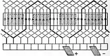
Coils of the winding are distributed over the entire surface of the air gap, which may be the rotor or the stator of the machine. In a "lap" winding, there are as many current paths between the brush (or line) connections as there are poles in the field winding. In a "wave" winding, there are only two paths, and there are as many coils in series as half the number of poles. So, for a given rating of machine, a wave winding is more suitable for large currents and low voltages.[6]
Windings are held in slots in the rotor or armature covered by stator magnets. The exact distribution of the windings and selection of the number of slots per pole of the field greatly influences the design of the machine and its performance, affecting such factors as commutation in a DC machine or the waveform of an AC machine.

Winding materials
Armature wiring is made from copper or aluminum. Copper armature wiring enhances electrical efficiencies due to its higher electrical conductivity. Aluminum armature wiring is lighter and less expensive than copper.
See also
References
- Stephen D. Umans, Fitzgerald's and Kingsley's Electric Machinery - 7th ed, McGraw Hill, 2014, ISBN 978-0-07-338046-9, pp. 190
- "armature". definition of armature in English from the Oxford dictionary. Archived from the original on March 4, 2013. Retrieved July 17, 2015.
- "Basic AC electrical generators" (PDF). American Society of Power Engineers. Archived from the original (PDF) on 2016-03-03. Retrieved 2016-01-02.
- A.Van Valkenburgh (1993). Basic Electricity. Thomson Delmar Learning. ISBN 978-0-7906-1041-2.
- Armature reaction in DC machines, | electricaleasy.com
- Gordon R. Slemon, Magnetoelectric Devices: Transducers, Transformers and Machines, John Wiley and Sons, 1966, no ISBN, pp. 248-249